Presented by Nine Lives Racing
1 2
Gimp (Forum Supporter)
Gimp (Forum Supporter) GRM+ Memberand UltraDork
5/4/21 2:34 p.m.

So, over the winter, I (in theory) improved my rear spoiler - https://grassrootsmotorsports.com/forum/aerodynamics-presented-nine-lives-racing/prepared-rear-spoiler-how-badly-am-i-compromising/176944/page1/

Well, the rules for the front of the car have changed, and despite the current price of plywood, I'd like to take advantage of the new rules.

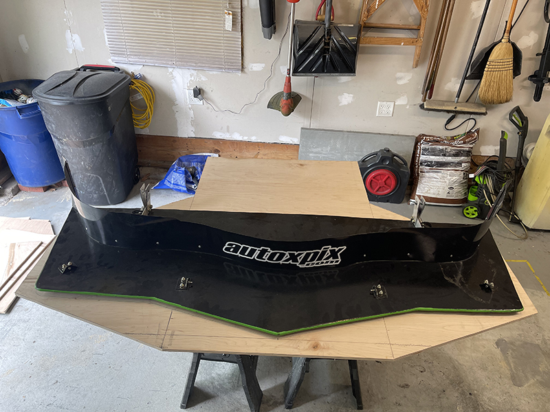
So, here is what I currently have, based on the previous rules (lots more details here - https://grassrootsmotorsports.com/forum/build-projects-and-project-cars/1981-camaro-c-prepared-build/59501/page31/):
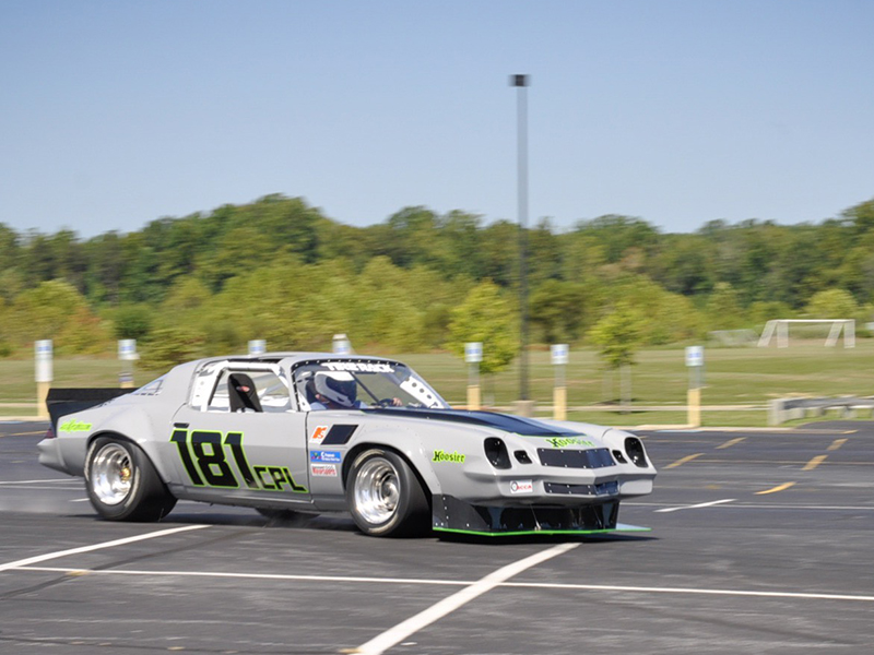
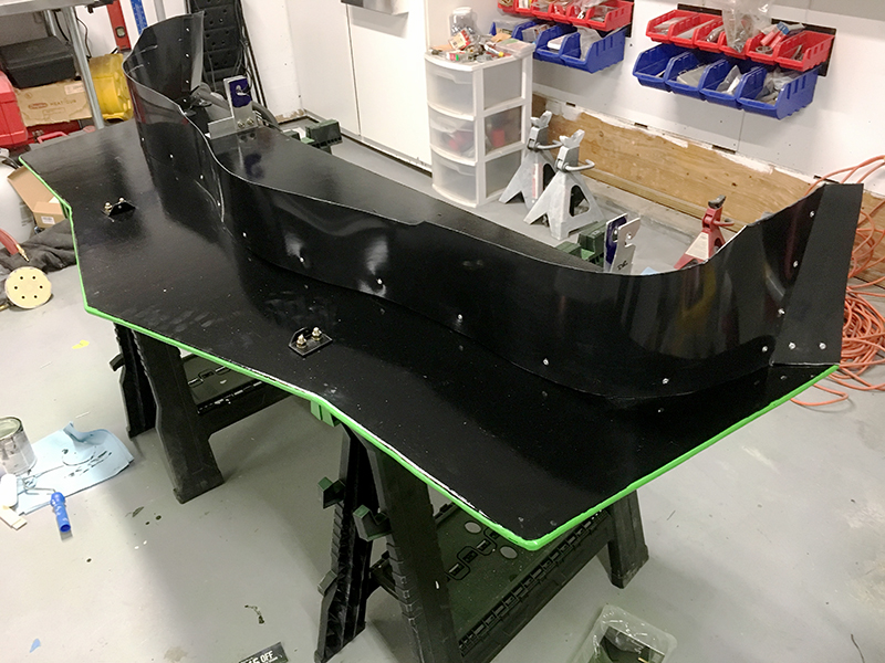
 

The most significant limiting factors that are no longer an issue are all related to size.  Previously, the splitter couldn't stick out past the bumper as viewed from above, and couldn't extend any further back than the opening of the wheel well.  The new rules change that, and add a few more options (emphasis mine).

The standard OE front spoiler or a non-standard front spoiler/splitter may be used. If a non-standard front spoiler/splitter is used it must comply with the following requirements: Shall be installed parallel to the ground (within ±3° fore and aft) and may extend a maximum of 6” (15.24 cm) forward of the front bodywork/fascia as viewed from above. Splitters may not extend rearward past the centerline of the front wheels axles. No portion of the splitter may be wider than/extend beyond the widest part of the
front bodywork/fascia from a vertical line drawn at the center of the front axles forward on the vehicle. The splitter and canards may have endplates.
The endplates may connect the splitter and the canard. The splitter and canard endplate total surface area is limited to 100 sq. in. (645.2 cm2) for each side. Canards are allowed and may extend a maximum of 6” (15.24 cm) forward of front bodywork/fascia as viewed from above. No portion of the canard may extend past the widest part of the front bodywork/fascia as viewed from above. Canard area will be measured in the same manner as wings using Section 12.10. Canard area may not exceed 1.2 sq. ft. (1114.8 cm2). Openings are permitted for the purpose of ducting air to the brakes, radiator, and/ or oil cooler(s); equal openings may be placed in the standard lower front panel directly behind openings placed in the spoiler/splitter. The spoiler/splitter may not function as a wing. This allows a vertical airdam/spoiler above a horizontal splitter.

So this leaves me with a few options and a lot of questions.

Question 1 - Front splitter profile.  Right now, the leading edge of my splitter follows the shape of the front bumper, because that was the rule.  Now, I can extend up to 6 inches forward of the bumper (more on that later), which opens up the shape of the profile.  I've seen a few different shapes, and I understand why some are like that, but I wasn't sure if there is an advantage to a particular shape.

  • Rounded - looks pretty and is doable within my limits
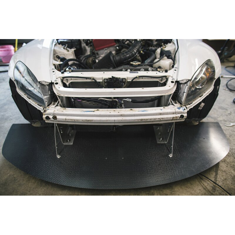
  • Geometric - gives more surface area, looks cool, and allows for more clearance when going around things
  • Flat/squared off - pretty extreme and can look either cool or weird.  Possible to pull this off, but I would have to do some measuring
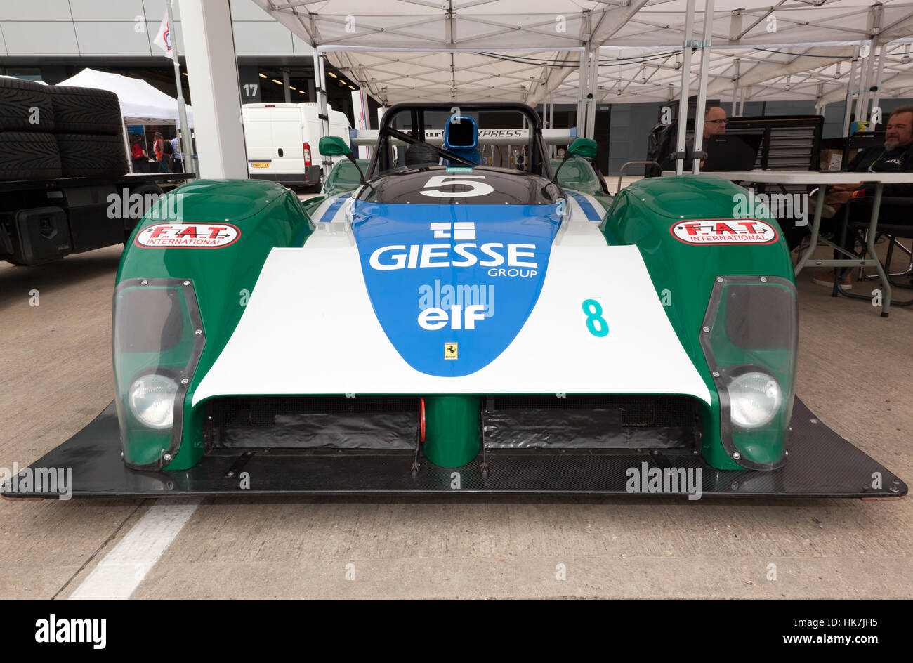


Question 2 - Length.  The shape chosen will dictate some of this, but I'm now allowed to stick out 6" further than before.  on most modern cars, this would be a no  brainer, but as you can see the front of my car has a lot of "overhang" and already has a significant amount of "shelf" before the air dam, depending on where you measure (9" at the ends, and 11" at the center).  Does adding another 6" of "stick out" to that surface really do much for me, downforce-wise, at this point?


Question 3 - Overall width.  I can now be as wide as my front fender flare at the center of the wheel - that's pretty wide.  To me, going wider means more of a chance of hitting cones.  Is there a significant advantage to going much wider than I am now?


Question 4 - End plates.  I'm allowed to run splitter end plates, with a maximum surface area of 100sq inches (combined with any canards).  I know I want end plates, but I'm not sure on the size and placement.  I've seen a few recommendations of no taller than 4 inches - I'm great with that, but do I put them at the front of the splitter to gather the air there, or place them at the back, closer to the tire? 

What about end plates with a stepped design vs flat?
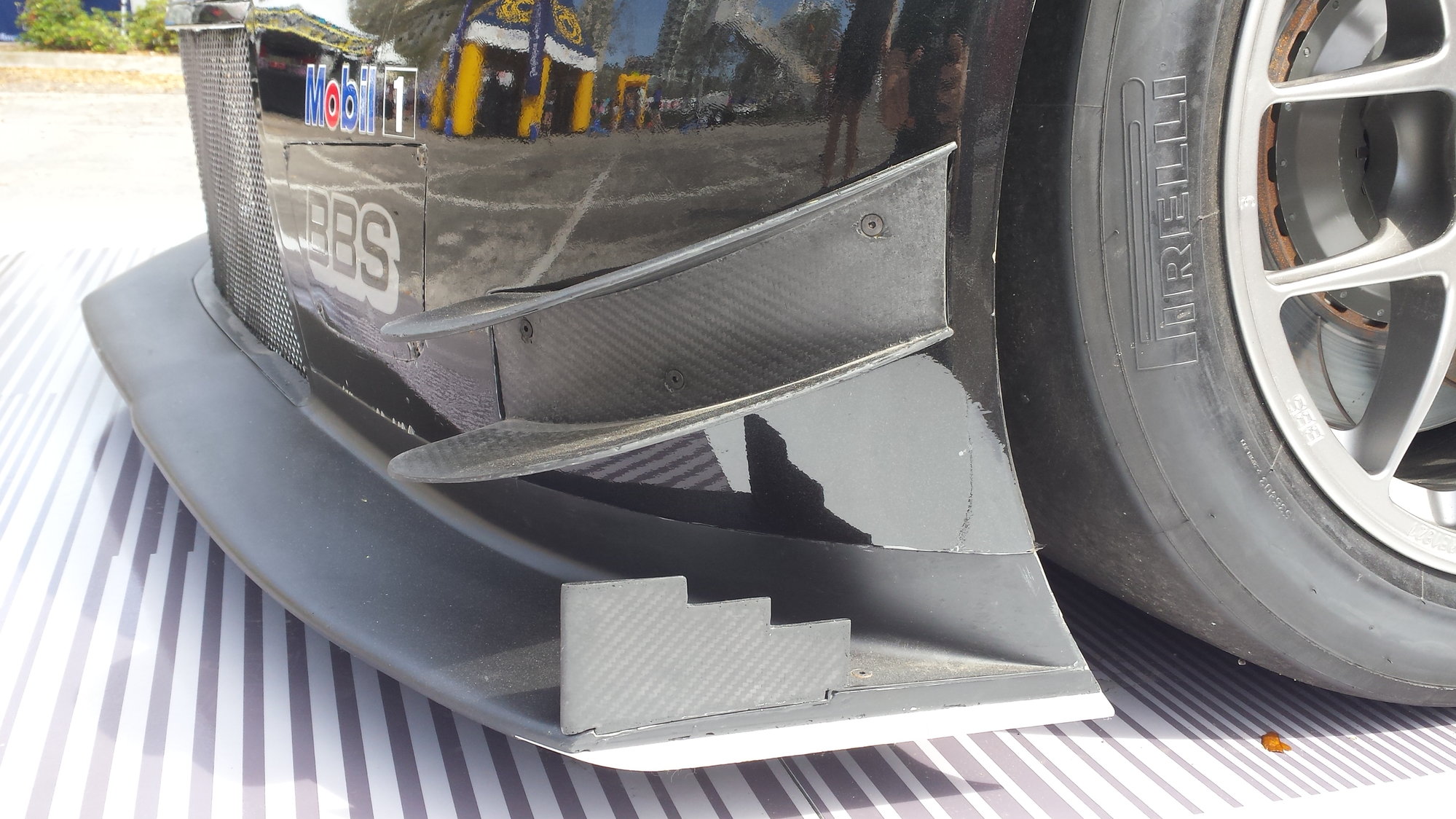
 

Question 5 - Canards.  Frankly, I don't even know where to start with these and really don't know if I should bother for this application.


The only thing I'm sure of at this point, is I will be extending the splitter further back to the wheel centerline to clean up the air there.  The rest is pretty open. 


I'd love to hear everyone's thoughts on where to go with this thing.  I'll be starting soon, as plywood isn't getting any cheaper.  Thanks!

stafford1500
stafford1500 GRM+ Memberand Dork
5/4/21 4:45 p.m.

I am going to reread this post a few times and I will put something together that may help point you in the right direction.

stafford1500
stafford1500 GRM+ Memberand Dork
5/4/21 6:17 p.m.

Let me see if I can get your questions answered/directed in the same order you asked them and maybe a few other ideas.

  • Question 1 - Front Splitter Profile: The profile you are going to want is the one that keeps you from hitting cones as you corner, gives you enough front downforce to balance the rear you have, and does not bottom out under braking or heavy aero load. The geometric shape is not too different from your current splitter at least style wise. The rounded version does not really give any distinct aero advantages other than it will more closely match the pressure profile ahead of the car. The flat/squared off version is going to be the path for maximum front downforce.
    • The rules also mention an angular tolerance of +/-3degrees. A nose down attitude will gain front downforce at high splitter gaps, but you want the splitter to end up close to parallel when you are at low splitter gaps, typically under braking. Low splitter gaps in most cases means less than 1" clearance.
  • Question 2 - Splitter length:  Since the new rules allow up to 6" of extension beyond the forward most point on the car, you are looking at the ability to increase the splitter area outside the car by ~350 sqin (includes the extra material from centerline out to the bumper corners being extended to the max). You are also going to be able to add ~300 sqin between the front wheels. That is a whole lot of area to work at even a fraction of a PSI of suction.
    • More length is going to mean more bending loads. you are going to need more bracing for any extra length. You may wind up with the corners getting worn down under heavy braking cornering. That would help drive your shape discussion above.
    • The extra length does two major things: it provides more surface area for the realtively high pressure on the top surface compared to the lower pressure on the bottom. This amplifies the effect and shifts the aero balance forward pretty significantly.
  • Quaetion 3 & 4 - Overall width & End plates: Increasing the width, like you mentioned will impact you cone contact cornering abilities. The area out board of the fascia is not going to be massively important unless you can get more fore-aft angle than allowed by the rules. You may want to consider the geometric shaping of the ends to the full width allowed and tie in the end plates and extending the wheel arch down to the splitter. This will give a large area of high pressure on the splitter and increase the extraction for the bottom of the splitter/wheel opening.
  • Question 5 - Canards (French for Geese): Canards or Dive planes can be very effective at creating front downforce, but are typically very high drag. They would have to be mounted at some pretty significant angles (~30deg from the ground) and need some curvature to keep the edge vortex spooled up on the bottom  surface. That vortex is very low pressure and is the source of the drag because you are working the air very hard away from it's lazy course of going around the car. They typically do not need to be mounted with the trailing edge much higher than the center of the front wheel, since the wheel opening shape angle starts to roll off above that area. The splitter endplate mentioned in #4 above will give a similar result if it is made taller than it is long. Dive planes are usually the first casualty during cone impacts! That leaves you with less downforce and parts to repair/replace. I would leave them off until you get to a point of limited front grip.

That pretty much covers your questions. Now lets consider some other things.

  • What is your balance currently? Balance is going to be the main deciding factor in how much more splitter you really need/want. If you need more front then extra splitter is the right direction. If you never have understeer, more front is not going to help until you get more rear grip. The extra splitter material on the back edge is going to provide you some more front. You may want to design a maximum area splitter and another that is half way between max and what you currently have. Try all of them at a test/event and see what you feel in the changes. A test and tune day would be great for this. You will also find out what the contact limits are for the current setup (you will probably find the corners get worn pretty badly on the max size).
  • Pretty much any adjustable feature you can build into a splitter will give you a way to tune the front downforce. If you can make the adjustment a sliding feature, you may be able to hot-swap differnet extensions for the tuning. Try to make those sliders part of the support for the extensions (the supports will also act as fasteners to keep the extensions attached to the car).
  • You did not see it here but, you may be able to take advantage of the high forces involved and use some spring loaded supports to get the splitter angle nose down at high speed (autocross relative) and returns to flat-ish at low speed. You have old valve springs right? This will be considered a moveable aerodynamic device, so you decide how deep you want to go. There are plenty of other ways to make a reasonably stiff flat structure move in ways to benefit downforce. Time for reasearch...
  • For fine tuning, use the same slider adjustment type of idea for the rear of the splitter. Since it is further aft, it will be less of a brute force change and move balance less for a similar downforce created at the front edge. 
  • You may want to consider materials other than wood for some of your splitter structure. Wood is a great material for those high wear areas, but fiberglass, metal and carbon fiber should be considered. They can be designed/tuned to flex in directions that benefit you (seems like I said that already...).
  • Leading edge radius. You want one. It needs to be pretty significant and kept clean. This edge sets up the flow for the entire under surface. If you can get a full 3/8" radius from the top to the bottom, great. If you have to give up on one side, sacrifice the top edge and get as much as you can on the bottom edge. The leading edge radius is less important as you get further away from the center, mostly from the inside edge of the tires to the outboard edge of the splitter.

That should give you plenty of reading/thinking material. Put you ideas back up here when you start to get a plan together.

Gimp (Forum Supporter)
Gimp (Forum Supporter) GRM+ Memberand UltraDork
5/5/21 7:47 a.m.

Thank you. This is an incredible response with a lot of think about.  I'm going to try get some of those thoughts together and I'll report back, but I wanted to make sure to acknowledge your help first!

Gimp (Forum Supporter)
Gimp (Forum Supporter) GRM+ Memberand UltraDork
5/24/21 8:47 a.m.

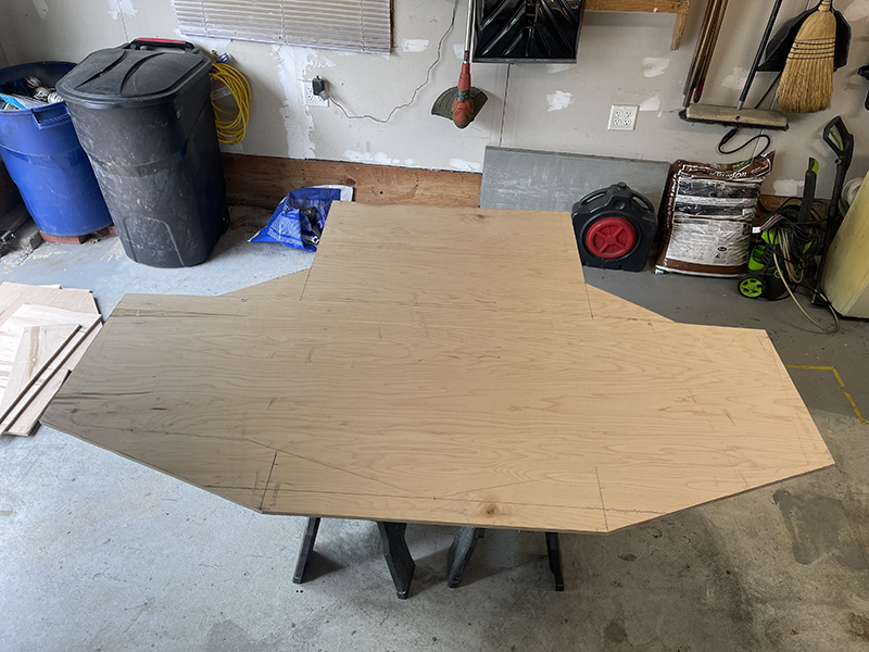
So, I went and bought some plywood, and after my heart rate settled from the sticker shock, I got to work.

I laid the old splitter on the new piece of 1/2" investment board and traced the old shape, and then played with the various profiles and surface areas discussed above.  I wound up settling on a shape that should still provide plenty of cone clearance while turning, but still increase surface area.  I also elected to keep the same width, mainly for the same reasons.


This is still within the 6" rule, but should increase the surface area by a good bit.  I didn't want to go too nuts and wildly shift the balance, but I'm hoping this will work well with the newly designed rear spoiler.


It's a little long, at the back, in this shot.  I wound up trimming about 6" off the back to keep it ahead of the front wheel centerline.


Pretty happy with the results so far.  It's already in primer and should be ready for the first event of my season, assuming the rest of the car is ready.

stafford1500
stafford1500 GRM+ Memberand Dork
5/26/21 8:04 a.m.

Looking good

Gimp (Forum Supporter)
Gimp (Forum Supporter) GRM+ Memberand UltraDork
6/8/21 3:10 p.m.

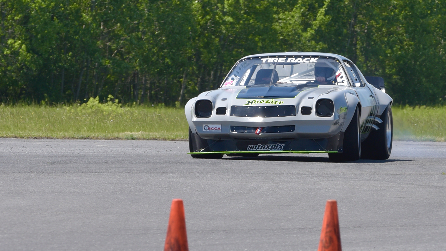
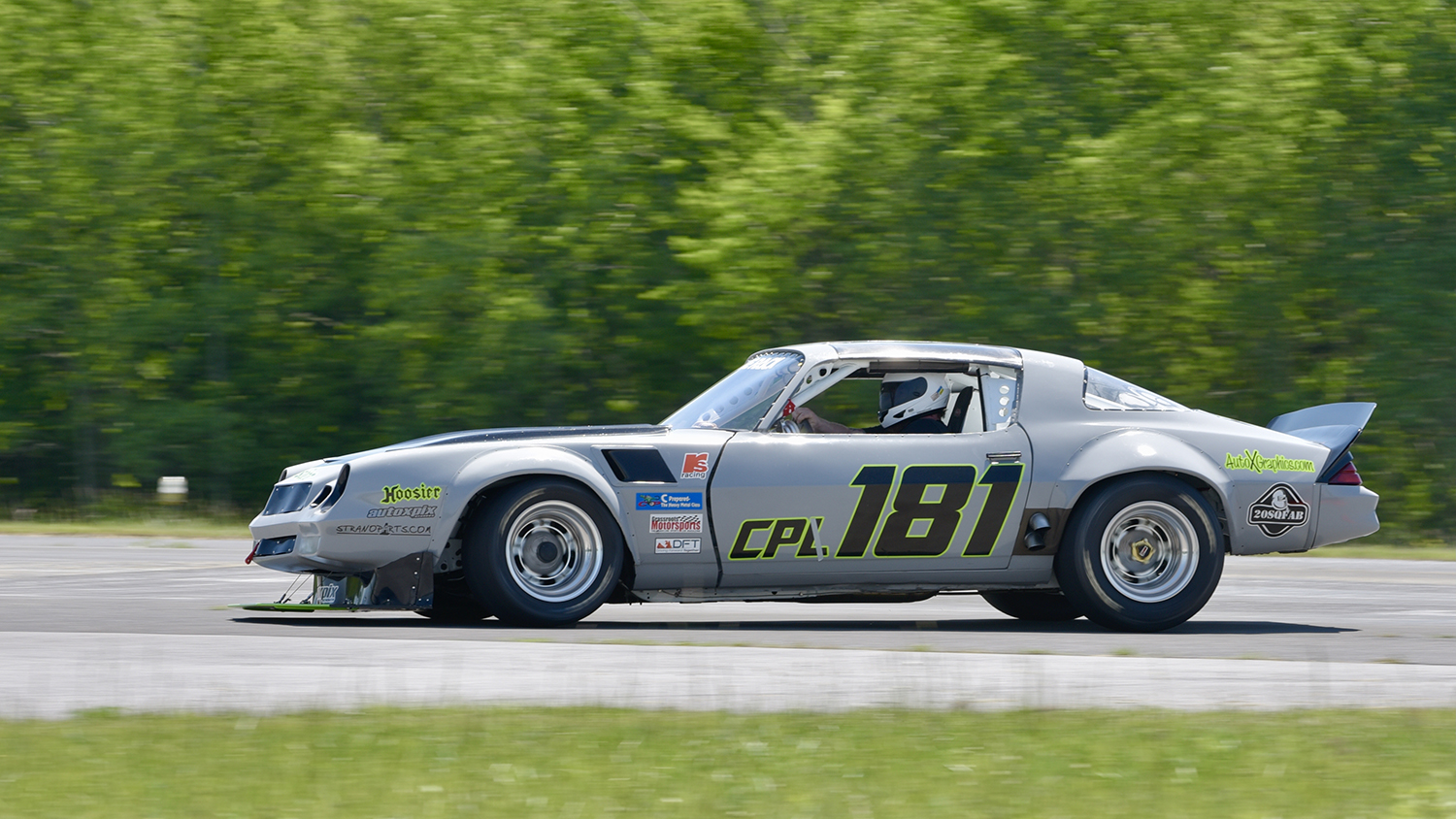
New splitter in action.  I did compromise on width, and this weekend proved that I was glad I did.  End plates are arriving soon and I'll have some questions about that, but for now, some action shots.


sleepyhead the buffalo
sleepyhead the buffalo GRM+ Memberand Mod Squad
6/8/21 3:55 p.m.

I watched the runs videos in the build thread.  looked like most of your cornering speeds were down around 45-50mph... so it might have been difficult to detect an aero effect/balance

is that sticking out forward enough that it means any wider and you'll start jinsuing all available cones?

Gimp (Forum Supporter)
Gimp (Forum Supporter) GRM+ Memberand UltraDork
6/8/21 10:00 p.m.
sleepyhead the buffalo said:

I watched the runs videos in the build thread.  looked like most of your cornering speeds were down around 45-50mph... so it might have been difficult to detect an aero effect/balance

is that sticking out forward enough that it means any wider and you'll start jinsuing all available cones?

Pretty much.

One thing to keep in mind is that this isn't a nationals course, and I wasn't driving my best, so we can assume that cornering speeds are going to be about 10 to 15 mph faster than you saw that video.

That said, any wider and I think I'm going to be paying a penalty with cones, so the goal here is to maximize the efficiency of what I have. I'm going to get some photos tomorrow, and hopefully we can do some magic with end plates to make the splitter a little bit better.

Yes I could be a little bit wider and get more surface area. I could also block more of the tire, but again, with the speeds we are talking about I think the impact is minimal.

The other thing to remember is I can't do much more with a rear aero, so will be really easy to overbuild the front and overpower the rear.

Gimp (Forum Supporter)
Gimp (Forum Supporter) GRM+ Memberand UltraDork
6/9/21 8:52 a.m.

So like I mentioned above, I am "compromising" on a few things with this splitter, but that is both for the sake of balance and for use.  Much wider and I'll be getting myself into cone trouble for sure.  I'm also worried about overpowering the rear aero by maxing out the front.

So, the intent here is to maximize what I have created so far, and that means end plates.

Here is where we stand now:


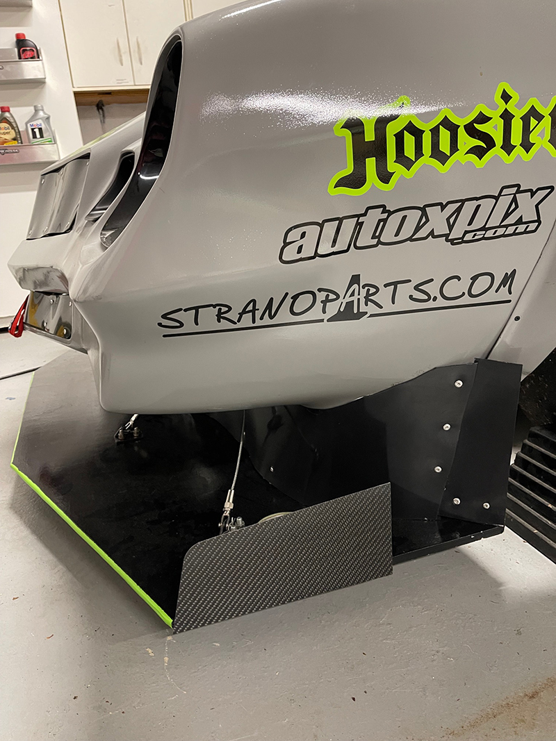
Basically, it's the same width as the old CP rules where it meets up with the wheel well (same width as stock body).  I have some plastic in there to make up an air dam that meets up with the front flare.  When I was first thinking of end plates, I was assuming the "best" position for them would be at the back of the splitter, meeting up and even connecting with the air dam:


Well, after some beers, my buddies and I decided we are armchair aero engineers, and thought that a forward position might be better.  The thought behind this is it will help air pile up on the front of the splitter, but give it a smooth escape path at the back of the splitter.


So, while those beers were really good, I figure I should post in here and get some real advice on which position is better.  Thanks!

sleepyhead the buffalo
sleepyhead the buffalo GRM+ Memberand Mod Squad
6/9/21 9:10 a.m.

looking at the rules snippet above, which references 100sqin per side... and guessing that carbon panel is ~9"x4"... then I'd guess you're only using half your alotment of endplate per the rules

I have another question, that (forgive me) flows into this: Is there a regulation on how the "airdam" can formed & positioned (mainly in the front/middle)?  Does it have to drop down from the bottom lip of the front bumper, and follow that contour?

Gimp (Forum Supporter)
Gimp (Forum Supporter) GRM+ Memberand UltraDork
6/9/21 9:27 a.m.
sleepyhead the buffalo said:

looking at the rules snippet above, which references 100sqin per side... and guessing that carbon panel is ~9"x4"... then I'd guess you're only using half your alotment of endplate per the rules

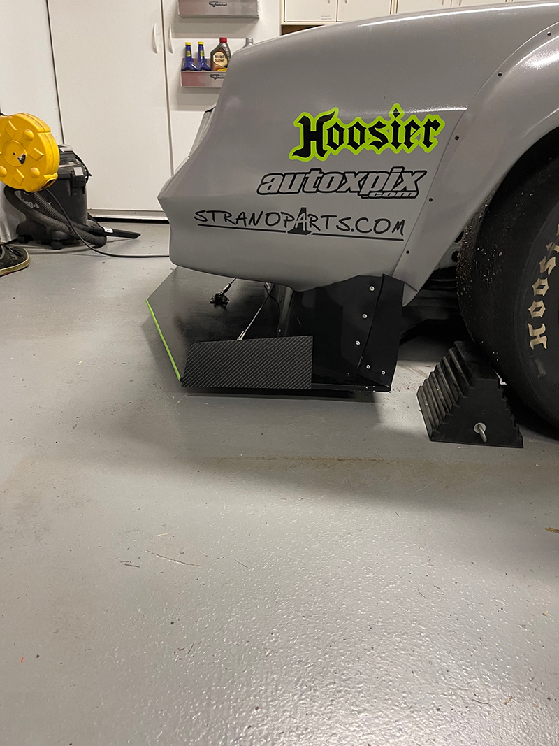
They are 11" long, 5" tall at the back, and 4" tall at the front, but yes, at the moment that is half of what is allowed, but I'm starting there so that I have ~45sqin per side in canards to play with if we wanted to.  Also, these were cheap and off the shelf.  I can always make bigger later if I'm happy with things.

sleepyhead the buffalo said:

I have another question, that (forgive me) flows into this: Is there a regulation on how the "airdam" can formed & positioned (mainly in the front/middle)?  Does it have to drop down from the bottom lip of the front bumper, and follow that contour?


No need for forgiveness on a good pun.  As far as the regulations on the air dam, I don't think there is much concerning position, but, if I go any further forward I'll be blocking the feed for the radiator (it breathes from under the nose).  I don't think it needs to follow the contour, but obviously currently does.

sleepyhead the buffalo
sleepyhead the buffalo GRM+ Memberand Mod Squad
6/9/21 10:19 a.m.

so, I reckon stafford's probably got a better feel for the endplate position benefits.  so, I reckon that both positions will "increase downforce";  but I think forward will maybe reduce drag more than make more downforce... compared to back, which I'd surmise will create more downforce but also more drag.

I'd guess that maybe getting the airdam to be "flat" instead of angled and then butting the endplate up against it would create the most downforce... outside of a full length endplate.  But, I'm not sure you're allowed to shape the airdam in that way, since there's probably a generally understood principle that the airdam should meet up with the fender flares.


re: airdam, centrally.

there's some miata OpenFOAM data that was done ~8 years ago by (iirc) Hancha and Verus, that....

{ insert sound of record scratching }

and, as I was typing this up, I think I realized an non-explicit discontinuity in the data they presented... and I might have to go hunt for more information. to decide if what I was going to suggest is actually helpful.

does this mean your radiator pulls air in from the underside of the front bumper... proboscis?

Gimp (Forum Supporter)
Gimp (Forum Supporter) GRM+ Memberand UltraDork
6/9/21 10:24 a.m.
sleepyhead the buffalo said:

does this mean your radiator pulls air in from the underside of the front bumper... proboscis?

Yup.  It's a bottom feeder.  The front grills are totally blocked off.

Apexcarver
Apexcarver UltimaDork
6/9/21 10:43 a.m.
sleepyhead the buffalo said:

so, I reckon stafford's probably got a better feel for the endplate position benefits.  so, I reckon that both positions will "increase downforce";  but I think forward will maybe reduce drag more than make more downforce... compared to back, which I'd surmise will create more downforce but also more drag.


That sounds right to me, but i havent spent much of any time with a wind tunnel

Gimp (Forum Supporter)
Gimp (Forum Supporter) GRM+ Memberand UltraDork
6/9/21 10:49 a.m.

I also feel like I can overcome drag with power, so I tend to lean towards more downforce.

Gimp (Forum Supporter)
Gimp (Forum Supporter) GRM+ Memberand UltraDork
6/9/21 2:46 p.m.

I thought I'd add another argument for why I'm (at least for now) sticking with the width I have:


Now, while this is over a bump, I do have scrapes at the back corners of both sides.  Adding 5" of width (which would be my max) to EACH side would really put these things in peril, let alone grab a few more cones.

If we decide down the road that I need more front grip and we should widen things, then it's a good excuse to buy a biscuit joiner.

Gimp (Forum Supporter)
Gimp (Forum Supporter) GRM+ Memberand UltraDork
6/11/21 8:21 a.m.
sleepyhead the buffalo said:

{ insert sound of record scratching }

and, as I was typing this up, I think I realized an non-explicit discontinuity in the data they presented... and I might have to go hunt for more information. to decide if what I was going to suggest is actually helpful.

I'm still curious to hear your ideas...

sleepyhead the buffalo
sleepyhead the buffalo GRM+ Memberand Mod Squad
6/11/21 11:58 a.m.

In reply to Gimp (Forum Supporter) :

apologies... I've got a lot of distributed items being juggled, currently

so, the wonder I have, is if pushing the airdam forward in the middle would help increase the radius of the airdam.  The thought being that, then the flow 'trapped' between the splitter and what's left exposed of the front bumper would have an easier time 'turning the corner' and then being used 'for good' on the way out past the wheel.

that might be a tricky thing to suss out, though, with your radiator intake the way it is.  is that the way the air comes in from the factory?  is there a stipulation that you continue to bring air to the radiator 'via the factory opening'?

Gimp (Forum Supporter)
Gimp (Forum Supporter) GRM+ Memberand UltraDork
6/11/21 1:14 p.m.

No need to apologize.  You're helping me.

is that the way the air comes in from the factory?  is there a stipulation that you continue to bring air to the radiator 'via the factory opening'?

That is how it works from the factory.  They primarily breathe from the bottom, but the upper grill is also open (the lower is fake).  I have both the upper and lower closed off right now for aero reasons.

No stipulation, as far as I know.  I can even do a rear radiator, which is a well-in-the-future project.

stafford1500
stafford1500 GRM+ Memberand Dork
6/12/21 7:21 p.m.

Been a busy few weeks for you. Glad to see you got some track time with the new splitter. The end plates will make more downfore by sealing to the fender edge, but you have area to work with and you can make it a bolt fill panel.

The idea of pushing the valance forward in the center is problematic because of you rad intake and will not significantly change the flow around the nose at autocross speeds. It helps that you are pulling some air for rad cooling because it effectively forces the incoming air to turn around the car later, giving higher pressure over a wider part of the splitter.

Glad you saw the benfit of sacrificing width, both for cone strike and ground strike reasons.

Keep it up.

Gimp (Forum Supporter)
Gimp (Forum Supporter) GRM+ Memberand UltraDork
6/21/21 9:50 a.m.


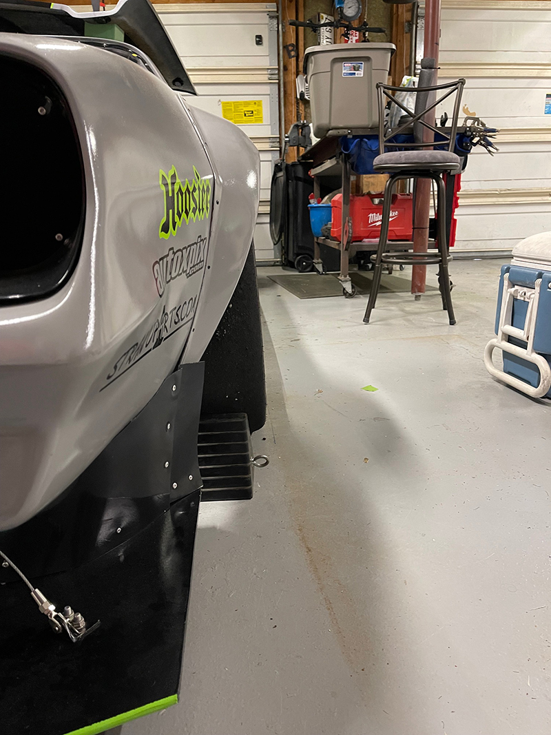
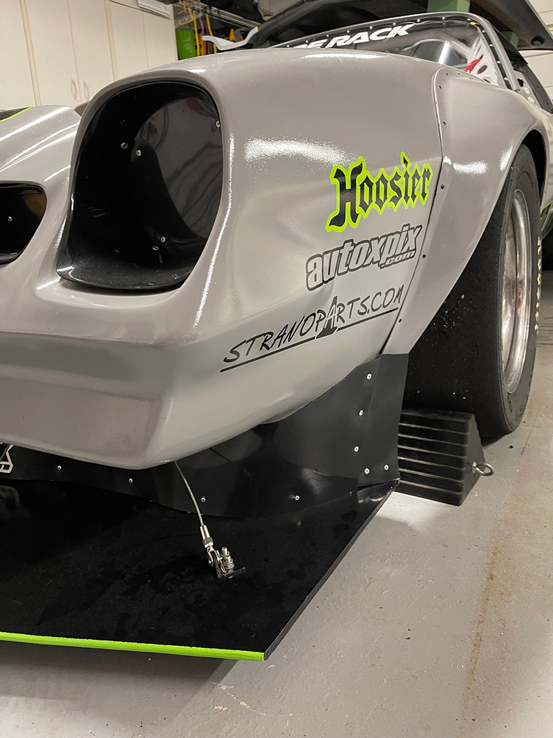
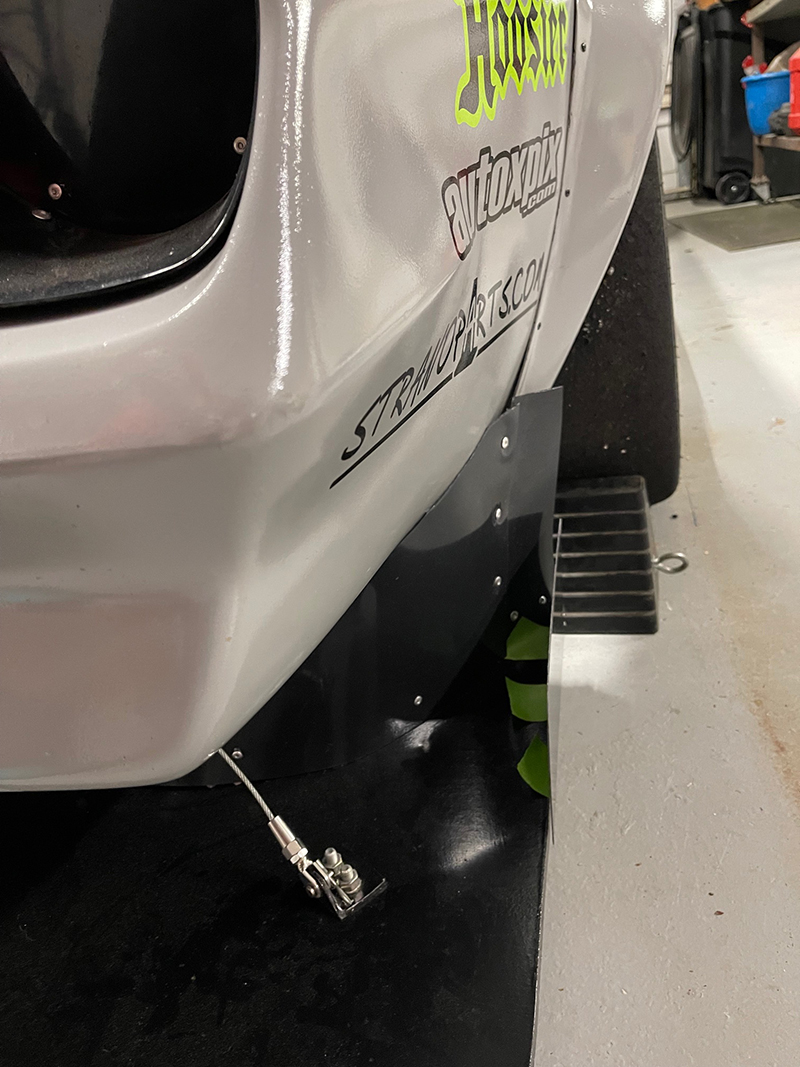
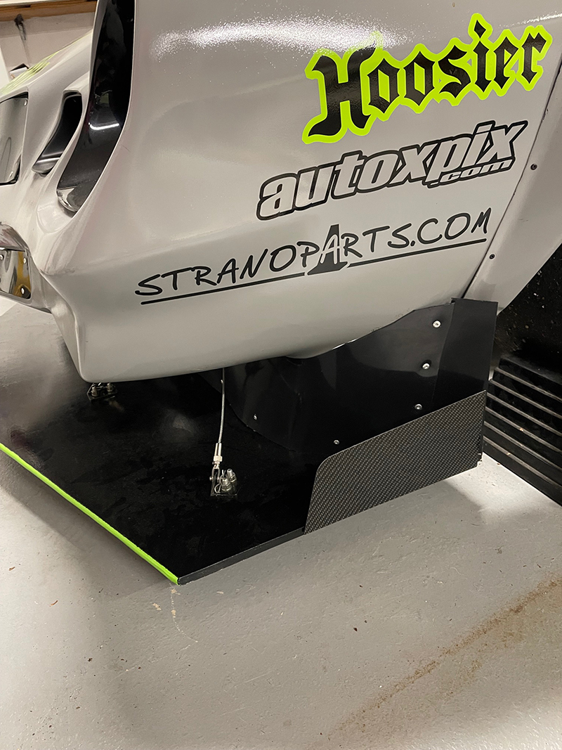
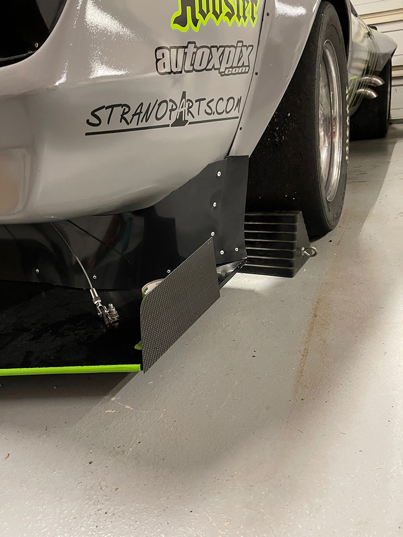
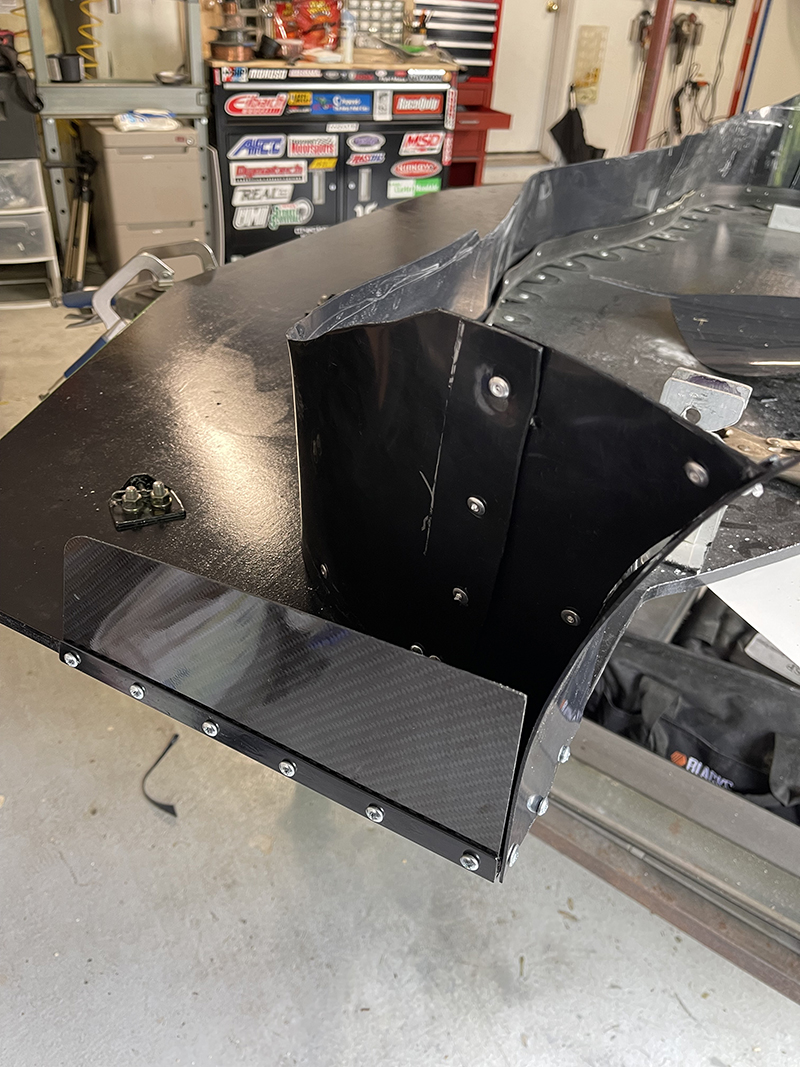
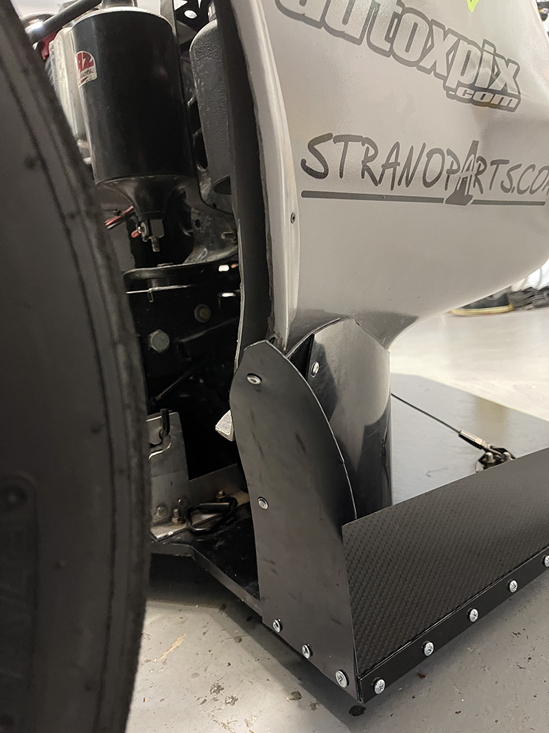
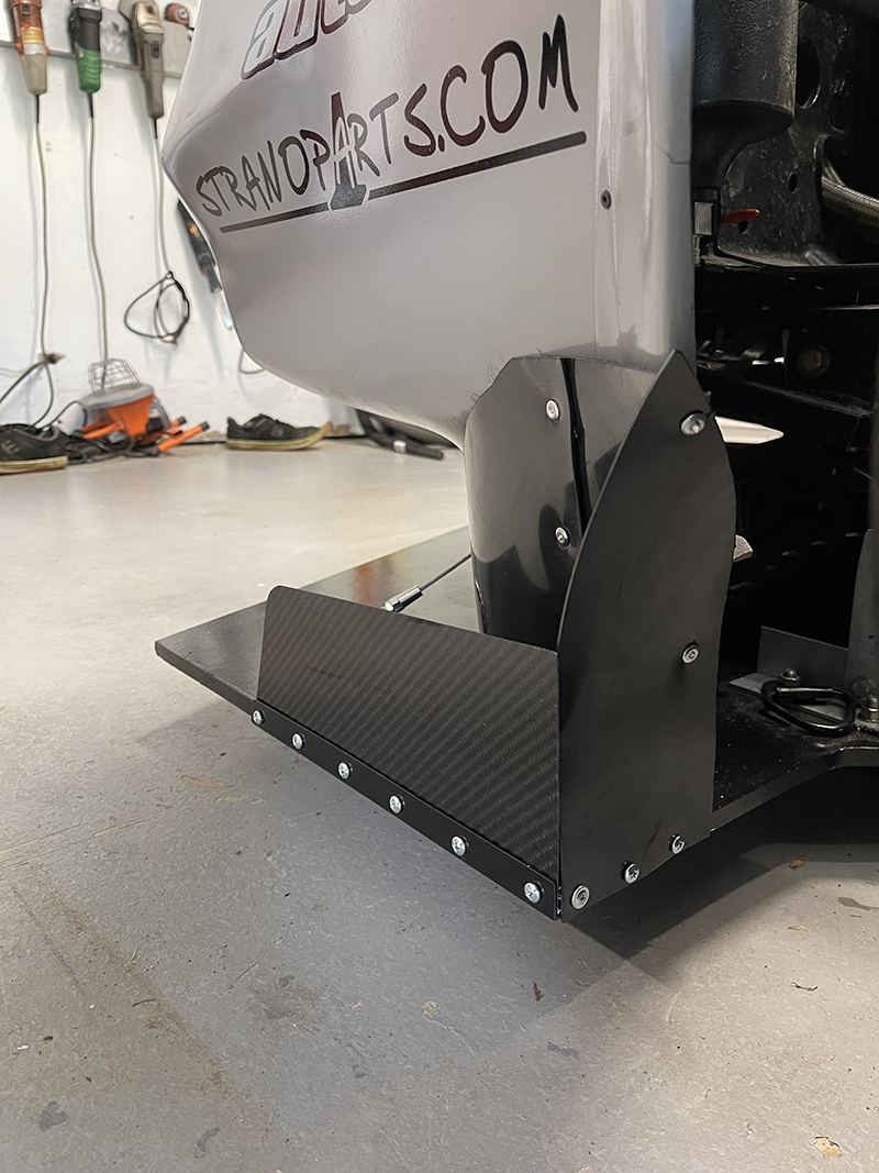
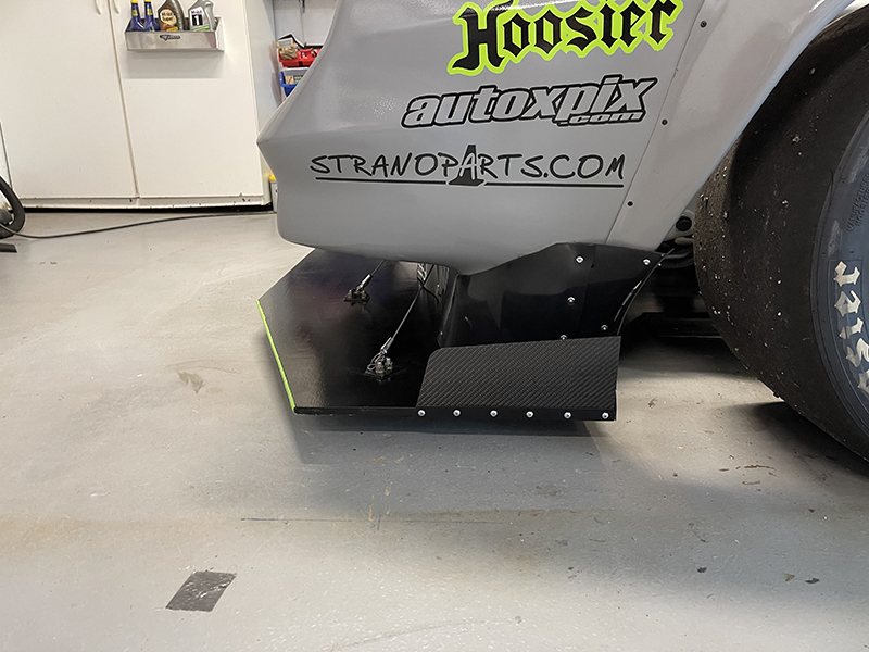
"Final" refinements for the new front splitter were done this weekend.  I added the endplates (they are about half the allowable size - that will stay that way for now) and then reworked the ends of the air dam to include a vertical fence between the air dam and the endplate, to better catch the air and shield some of the front tire.

I used the same plastic that I used on the air dam, and I only drilled into my hand twice!


I hate having screws in front of the tires like that, but it's my best option right now.  I may epoxy over at least the back ones...


Overall, I'm really happy with how things turned out.  Not sure if I'll notice a difference, but I know it's better. Thank you to everyone here for all of your help!

sleepyhead the buffalo
sleepyhead the buffalo GRM+ Memberand Mod Squad
6/21/21 10:10 a.m.

In reply to Gimp (Forum Supporter) :

I would tape up the seam between the endplate and the vertical bit; and between the vertical bit and the edge of the air dam.  black gaffer tape, or even painters tape should probably hold, and help keep the air doing what we want it to do

Gimp (Forum Supporter)
Gimp (Forum Supporter) GRM+ Memberand UltraDork
6/21/21 10:21 a.m.
sleepyhead the buffalo said:

In reply to Gimp (Forum Supporter) :

I would tape up the seam between the endplate and the vertical bit; and between the vertical bit and the edge of the air dam.  black gaffer tape, or even painters tape should probably hold, and help keep the air doing what we want it to do

Good advice.  I have been considering that, but I wasn't sure if it would have a real effect or just placebo.

Barb_Dwyer
Barb_Dwyer New Reader
7/28/21 4:45 p.m.

In reply to Gimp (Forum Supporter) :

It also seems like I can overcome drag with power, which makes me lean toward more downforce.

1 2

You'll need to log in to post.

Our Preferred Partners
YSoECJKmMVoKLNsMfpmtCbHDRwBUklupuV0789lduy2I5tD2H1P3c3qLcl9E49Zq