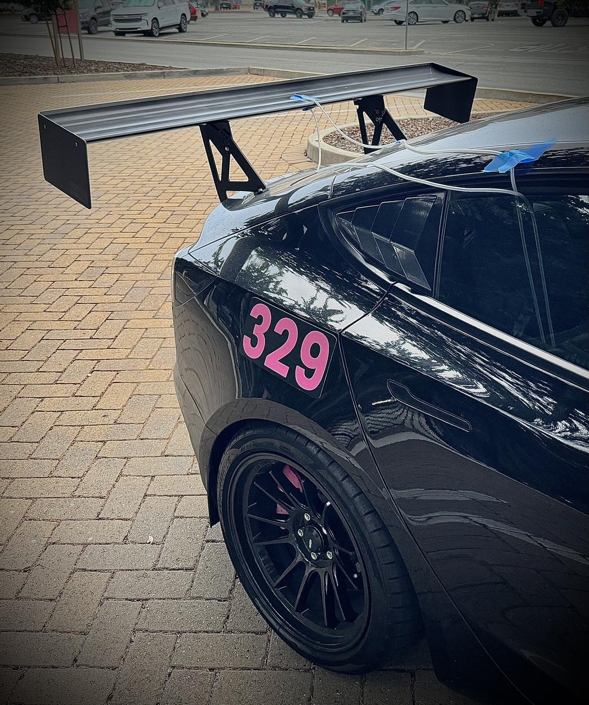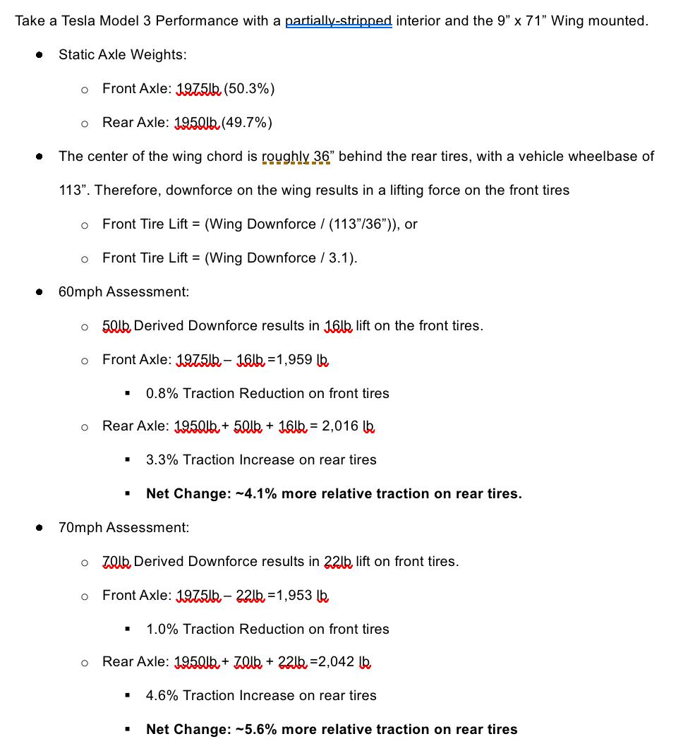
I posted this in my build thread, but thought it might be a good reference here.
I got to do a fun project for a statistics and modeling class. A buddy and I used a basic low-pressure gauge to measure relative vacuum and pressure on the top and bottom of my Nine Lives Racing Wing. This is a more interesting except from the larger project, which was mostly assessing about our ability to properly analyze data, with a nod to our ability to justify a position based on available data.
The desired end state of the wing was to generate an aerodynamically-induced understeer bias to reduce the chance of high-speed over rotation, increasing relative safety and driver confidence without sacrificing low-speed yaw rates.
(I got the idea from https://grassrootsmotorsports.com/articles/low-buck-aero-testing/ )
(Note: Given the rudimentary equipment and limited time available for data collection, these results are likely +/- 50%. That said, the published CFD results from 9LR are about 50% higher than ours, so these are probably still on the conservative side!)


Nice summary of your project and congrats on delving into the 'dark arts' of aerodynamics. I live there. The aero balance changes need to include the aero loads of the vehicle along with the static weights to give a more realistic result (what you will feel in the seat). However, they results are still promising and the direction is correct. Add in the drag of the wing above the CG height and you have more rearward balance shift.
If you want to get a little more geeky about your calculations:
The wing lift/downforce is generally assumed to apply at 25% chord, so move your applied load forward a bit. Typical pitching moment of wings is 'usually' stable around 25% chord. Not zero but stable.
The low pressure area is concentrated near the leading edge and will give larger pressure deltas if you are near the low end of the differential gauge. More magnitude results in better resolution.
The reported wing lift curves are likely done in isolation and at infinite aspect ratio (widthe to chrod). The fact that yours is connected to a car and is not infinitely long will reduce the performance. Your 50% reduction is not out of line.
Measuring the pressures at the centerline gives the likely worst case scenario due to down wash ahead of the section. The ends will see less downward from the approaching air and a lower angle of attack. You could add to your data analysis by capturing pressures over the quarter panels and applying a basic lift curve across the span of the wing.
Your pressure lines are most likely interfering with the measurements. Try routing the lines toward the trailing edge of the wing and down a pylon. The smaller the tubing you use the faster the response time will be allowing for a speed sweep or more stable data. The air in the tube is acting like a spring and can fluctuate. Shorter runs of tubing help too.
I have my car set up like that - mechanical oversteer, aero understeer. I've never tried to quantify everything, though, it's based on analog seat of tha pants testing.

stafford1500 said:
Nice summary of your project and congrats on delving into the 'dark arts' of aerodynamics. I live there. The aero balance changes need to include the aero loads of the vehicle along with the static weights to give a more realistic result (what you will feel in the seat). However, they results are still promising and the direction is correct. Add in the drag of the wing above the CG height and you have more rearward balance shift.
If you want to get a little more geeky about your calculations:
The wing lift/downforce is generally assumed to apply at 25% chord, so move your applied load forward a bit. Typical pitching moment of wings is 'usually' stable around 25% chord. Not zero but stable.
The low pressure area is concentrated near the leading edge and will give larger pressure deltas if you are near the low end of the differential gauge. More magnitude results in better resolution.
The reported wing lift curves are likely done in isolation and at infinite aspect ratio (widthe to chrod). The fact that yours is connected to a car and is not infinitely long will reduce the performance. Your 50% reduction is not out of line.
Measuring the pressures at the centerline gives the likely worst case scenario due to down wash ahead of the section. The ends will see less downward from the approaching air and a lower angle of attack. You could add to your data analysis by capturing pressures over the quarter panels and applying a basic lift curve across the span of the wing.
Your pressure lines are most likely interfering with the measurements. Try routing the lines toward the trailing edge of the wing and down a pylon. The smaller the tubing you use the faster the response time will be allowing for a speed sweep or more stable data. The air in the tube is acting like a spring and can fluctuate. Shorter runs of tubing help too.
Wow, thank you for the great info! I'll try again at some point with your recommendations! We also briefly played with a line taped to the center of the front bumper and found a notable positive pressure, but not sure where we recorded it. However, it is on the to-do list toward building an eventual splitter!
I hadn't even considered the additive effects of drag as well. To calculate its impact on F/R bias, would I set the fulcrum as the CG height (about 16.5" off the ground), the axle height (about 13" off the ground), or the tire contact patch?
Keith Tanner said:
I have my car set up like that - mechanical oversteer, aero understeer. I've never tried to quantify everything, though, it's based on analog seat of tha pants testing.
Yeah I just moved close to Laguna Seca so I'm setting it up for that without losing the twitchier mechanical settings that enable good rotation for autocross! I have heard reports that it's pretty easy to start inducing a lot of high-speed understeer with these larger wings; hopefully as I gain more confidence and familiarity, I can start adding some front aero as well!
Apply the drag force induced moment at the ground. That's where you are trying to resolve the total vertical forces.

jcc
New Reader
1/12/25 1:27 p.m.
In reply to stafford1500 :
I would also suspect simply raising the wing any amount into into cleaner air, will achieve both greater DF AND a larger drag moment you note for the OP to help achieve his intended goals, and then tune the wing with AOA..
What is not clear to me is the drag induced moment calculated from the rear tire contact point or the rear axle centerline, others can clarify I hope
In reply to jcc :
I believe stafford1500 above was saying to set the contact patch as the fulcrum to calculate the resultant drag moment!


