1 ... 13 14 15 16 17 ... 47
nocones
nocones GRM+ Memberand SuperDork
9/21/15 10:27 p.m.

So are you telling the software you want in your first example 30.78* of steering on the left wheel and then it computes the other wheel? I can't quite decipher what you are inputting for steering anlge to determine what the software is doing.

If your arms are actually 1.5" below LBJ and you are running 10* KPI you need to move them another .3" ouboard per side to get close to 100% Ackerman. I would expect if you took the first model and put them .3 per side further outboard(seems to be the 26.5 number?) You would get really close to ideal Ackerman.

Your 3 runs have different total degrees of f turn. It does not appear the software corrects for that so your error is simply lowest in the run that had the least steering angle. It looks like your 3 runs just increased the lenght of the steering arms but left the distance from centerline the same. I'm very confused why the x dimension on the upper and lower are the same.. This software clearly works with a strange method of dimensional input.

Gimp
Gimp GRM+ Memberand SuperDork
9/22/15 8:18 a.m.
nocones wrote: So are you telling the software you want in your first example 30.78* of steering on the left wheel and then it computes the other wheel? I can't quite decipher what you are inputting for steering anlge to determine what the software is doing.

I'm setting the steering angle using the "steer" input in the upper right hand corner. For most of those previous images it is set to "1." I don't know what the unit of measurement for that is.

nocones wrote: If your arms are actually 1.5" below LBJ and you are running 10* KPI you need to move them another .3" ouboard per side to get close to 100% Ackerman. I would expect if you took the first model and put them .3 per side further outboard(seems to be the 26.5 number?) You would get really close to ideal Ackerman.

My steering arms are also the attachment point for the lower ball joint stud. So the arms themselves should be above the lower ball joint axis of rotation, before spacing the tie rod ends down for bump steer.

I'm starting to suspect that I measured the ball joint in the incorrect location. The instructions say that I should measure the height where I think the center of the ball is located. I wonder if I measured it on where the spindle sits on the stud instead. I won't be able to confirm this for a bit.

nocones wrote: Your 3 runs have different total degrees of f turn. It does not appear the software corrects for that so your error is simply lowest in the run that had the least steering angle. It looks like your 3 runs just increased the lenght of the steering arms but left the distance from centerline the same. I'm very confused why the x dimension on the upper and lower are the same.. This software clearly works with a strange method of dimensional input.

Honestly, the errors or strangeness are probably not a result of the software. Since I'm a programmer, I'm the first to blame the user.

As I read what you wrote - "It looks like your 3 runs just increased the lenght of the steering arms but left the distance from centerline the same." - that is correct, concerning what I did.

The X dimension you mention is the distance from the center of the car. It's the Z measurement, or depth, that is the same for the upper and lower ball joint points. Right now, when looking from above, I have those two lined up - in other words, 0 caster. All of that is determined using an eyeball, so you can assume there is a degree of error in there.

I want to take a second and tell everyone that I appreciate their help and patience in figuring this out. I know this isn't the sexy part of a build, but it should insure a very fast race car once I get it sorted. Hopefully I'm not the only one learning something here.

The_Jed
The_Jed UberDork
9/22/15 8:49 a.m.

I appreciate this part of the build being posted, the nitty gritty details that, once sorted, come together to make a fast car.

I'm definitely learning something!

nocones
nocones GRM+ Memberand SuperDork
9/22/15 1:05 p.m.

That makes sense. Reviewing pictures it looks like your steering link is essentially level (slightly above)with your actual lower ball joint pivot. Right now you are telling the software it is 1.5" below. Since you have 10 of KPI and you put in the lateral location as .5" ouboard of the balljoint the software is accounting for it being 1.5tan(10*) less outboard then that. So you have improved your Ackerman relative to your initial calculations but the error in height is reducing your Ackerman. Raise the tie rod height to match the LBJ and rerun case 1 from last night and I bet you get near perfect Ackerman.

Understanding the input for steering the 3 runs make a lot more sense. As he steering arm got longer the turn reduced and total Ackerman reduced also. Your Ackerman error seems to have actually went up sightly with each run because the total turning angle reduced and you didn't increase outboard dimension as you ran it.

I sketched up a possible modification you could do to the arms in sketchup last night that should make your arms work and be adjustable moving forward and will post it tonight.

I think units on steering input is just " of center member travel. With a 2" arm and 1" travel ~30* of wheel turn is a sensical solution.

Gimp
Gimp GRM+ Memberand SuperDork
9/22/15 1:13 p.m.

Thank you so much! I will totally re-run everything tonight and post it up.

I honestly never thought the end link height would make a difference on ackerman. I set it lower to reduce bump steer.

I would love to see the modification! I owe you a cold one!

nocones
nocones GRM+ Memberand SuperDork
9/22/15 11:34 p.m.

Ok so the idea for the modification. basically mill or cut the part down to where it is flat on the outboard side. Crossdrill some holes (similar to the mounting holes for the upright) and build a block that has your desired steering arm length (I modeled it at 4" in sketchup from your overhead picture). Bolt that block on. Now you can use shims to increase/decrease ackerman for fine tuning. You could also build different blocks for different steering ratios. I show the block as a large solid piece of aluminum but realistically you could probably make it out of 5/16-3/8 plate to accept the crossbolts welded to a piece of 1" stock reamed to accept your steering link bolt.  photo steeringarm_zpss1xikv7g.jpg

 photo steeringarm2_zps8oqao6tw.jpg

You can adjust where the steering arm is cut to make it thicker so it is stiffer, the block would just be thinner.

Also sketchup is awesome for this kind of ideation. This took me about 30-40 minutes and that's because I haven't used sketchup for a year (which honestly is why I did it I needed an excuse to play). I adjusted the size of your overhead view using the grid you painted so the part is actually to scale as are the holes. CAD is fun.

nocones
nocones GRM+ Memberand SuperDork
9/22/15 11:40 p.m.

 photo steeringarm3_zpsyjrptiyf.jpg

Couldn't resist making the alternate version with the thicker steering arm.

Gimp
Gimp GRM+ Memberand SuperDork
9/23/15 7:55 a.m.

Damn! That's way smarter than my idea to cut off the end of the steering arm and weld it to the side of the arm to get the distance I wanted. I don't see strength being much of an issue either.

I'd imagine I could give the bits to any competent machinist and they could whip it up.

Gimp
Gimp GRM+ Memberand SuperDork
9/28/15 12:08 p.m.

So I did drill the steering arms over the weekend. I did it close to the edge and around 4" forward, which will give me a little ackerman, but these arms will not be used in service, other than moving the car around right now. The hole is way to close to the edge and the geometry isn't idea. Coleman will happily make me an arm in whatever shape I need, so I'll order a set from them once I confirm everything.

Apexcarver
Apexcarver PowerDork
9/28/15 1:55 p.m.

In the meantime, get the brakes working so we can soapbox derby this thing!

Stang_guy03
Stang_guy03 Reader
9/28/15 2:40 p.m.
Apexcarver wrote: In the meantime, get the brakes working so we can soapbox derby this thing!

LOL!!!!

Gimp
Gimp GRM+ Memberand SuperDork
10/5/15 8:24 a.m.

That may not look like that big of a deal, but best I can recall, this is the first time this car has had one of those in 12 years.

The even cooler part? Turn that thing to the right, and the car does this:

Turn it the other way, and the car does this:

You wouldn't believe how happy this makes me.

So I went up this weekend with my "temporary" steering arms. After all the talk about ackerman, I just drilled the arms I had for max ackerman available to test my theory. These arms would fail almost immediately if I tried to race the car on them, based on how close the tie rod bolt is to the edge, but Coleman will make me custom arms to my spec, so I'll order those down the road before the car moves on it's own. Right now, totally steering is about 1.5ish turns lock to lock. Should be plenty fast.

With those in, I proceeded to lay out the steering linkage, which meant putting the mockup block in the car, attaching a header, and cutting some metal.

The splined u-joint attached to the steering box put up a HUGE fight going on, so I decided I should have another breakpoint in the linkage to get things apart. If you look towards the firewall, you'll see another splined coupler just before the firewall bearing (which will be put in for good, not just bungeed there, next time when I patch the firewall). This will let me get the column, with the firewall bearing, out from the inside if I need to.

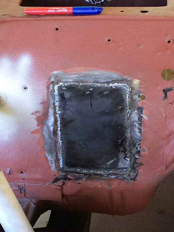
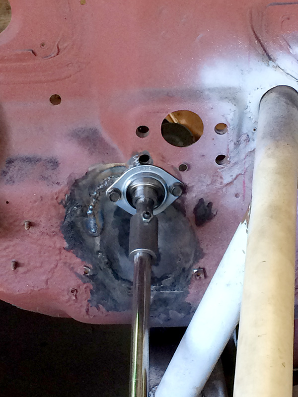
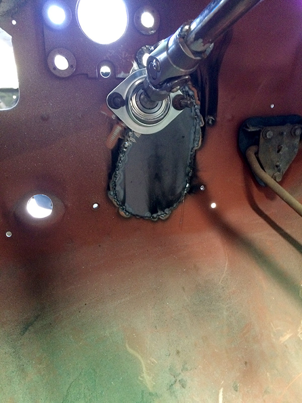
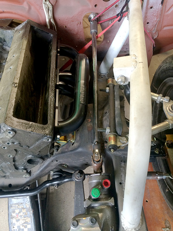
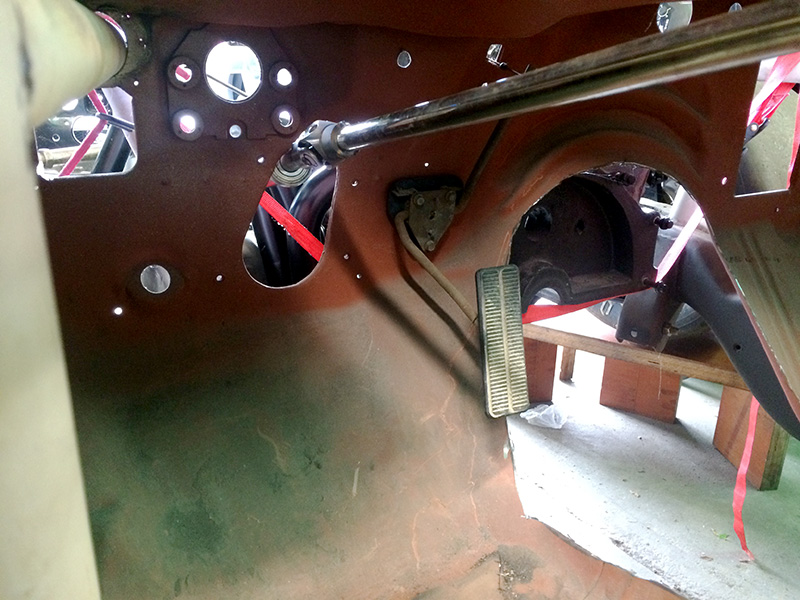
You can see here where it comes through the firewall. I'll patch the original steering hole next time, and mount the firewall bearing for good.

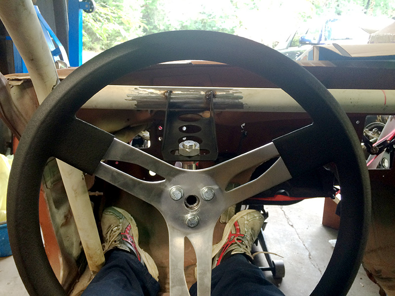
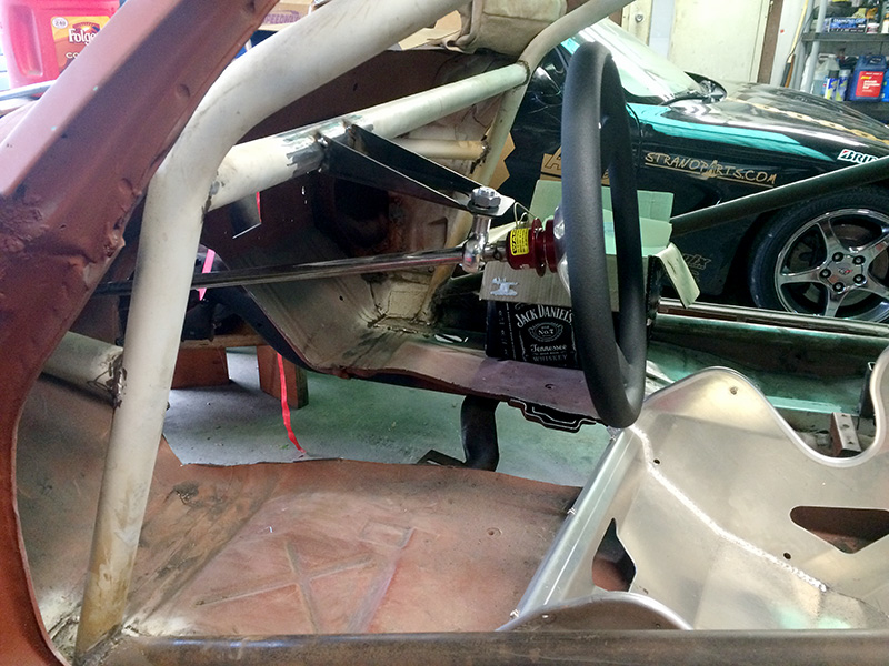
And finally - input. I had to flip the bracket I bought for the steering wheel to get wheel low enough. It was hard to take a picture of what you see, but the top of the steering wheel is about 1/2" tops above the dash in the line of sight. Should be perfect.

Frankenmaro
Frankenmaro New Reader
10/5/15 10:22 a.m.

Love this build! glad you figured out the steering. Keep posting.

nocones
nocones GRM+ Memberand SuperDork
10/5/15 9:18 p.m.

Yay that looks like real live Ackerman!

Gimp
Gimp GRM+ Memberand SuperDork
10/6/15 8:26 a.m.
nocones wrote: Yay that looks like real live Ackerman!

I know! It's getting there. Not quite to spec yet, but the new arms will fix that. At least I can put that baby down for a nap right now and knock a few other things out.

Next step will be relocating the upper control arm attachment points.

Gimp
Gimp GRM+ Memberand SuperDork
10/13/15 7:42 a.m.

I have a new found respect for those that do body work and rust repair. That job SUCKS, and I've just scratched the surface.

Went up yesterday, and Kate and I patched two large holes in the firewall. One is for the heater box and just needed to be plugged, but the other was for the steering. I had to close the hole up, then cut a new old for the firewall bearing. Long job welding and grinding sheet metal, but it's all in place.

I left some of the welds here undressed because the metal was getting thin.

And here is the backside, where you can see my other u-joint that gets things pointed straight at the driver.

Next trip up is in two weeks, and then we do some major cutting.

tdrrally
tdrrally Reader
10/16/15 11:49 a.m.

In reply to Gimp:

have you looked at the LS based 4.3? all aluminium and nearly 300hp on E85 stock

Gimp
Gimp GRM+ Memberand SuperDork
10/16/15 1:09 p.m.
tdrrally wrote: In reply to Gimp: have you looked at the LS based 4.3? all aluminium and nearly 300hp on E85 stock

I have had an eye out at LS options. Even with the lower weight I could run with the 4.3, I'd need to make around 500hp.

81cpcamaro
81cpcamaro Dork
10/16/15 3:03 p.m.

It's a CP car, great bodywork isn't required, and is usually discouraged. Bondo just ads weight to the car anyways.

The new 4.3L V6 is tempting, but Gimp is right 300 hp is back pack in CP. Heck 500 hp is slightly better than mid pack. Now if it were in my MGB, that would be another story.

Thinkkker
Thinkkker UltraDork
10/16/15 3:52 p.m.

500hp can get the job done. Though, that is with a small V8. So yea, 500 with a small V8, 625+ with a big one sounds about right ;).

Ill make a CP car one day. It wont have a roof, or a V8......

Gimp
Gimp GRM+ Memberand SuperDork
10/19/15 9:06 a.m.

I have t-tops... that's barely a roof.

NOT A TA
NOT A TA HalfDork
10/19/15 11:22 p.m.
Gimp wrote: Next step will be relocating the upper control arm attachment points.

While watching the thread I've been wondering if you were going to do this.

loosecannon
loosecannon HalfDork
10/20/15 12:00 a.m.

Put a Roots style blower on it, sticking out of the hood with the big cogged belt spinning away. Ok, I regained my senses now, carry on.

theenico
theenico Reader
10/20/15 9:08 a.m.
Thinkkker wrote: 500hp can get the job done. Though, that is with a small V8. So yea, 500 with a small V8, 625+ with a big one sounds about right ;). Ill make a CP car one day. It wont have a roof, or a V8......

Corvair?

Gimp
Gimp GRM+ Memberand SuperDork
10/20/15 9:10 a.m.
NOT A TA wrote:
Gimp wrote: Next step will be relocating the upper control arm attachment points.
While watching the thread I've been wondering if you were going to do this.

Yes sir. I have new brackets that will lower them, and I'll move them about a 1/2 inch back for more caster.

1 ... 13 14 15 16 17 ... 47

You'll need to log in to post.

Our Preferred Partners
1m8mAK50ayFgKegjK0T20b1vsYr5iRtPYJfUzEiUyhXLvZrLtNonZl7QJXwRKvIK