1 ... 8 9 10 11
NOT A TA
NOT A TA Dork
8/18/16 12:06 p.m.

It's been a few months since I updated this thread and a lot has happened so I've got some catching up to do. The short version is listed below with some quick explanations in the paragraphs that follow.

  1. Car still in my own self inflicted paint jail.
  2. Started a new company called Lab-14 making pieces to repair and/or strengthen structural parts of sub frames and other parts.
  3. The 14 Car is now sponsored by PRO-TOURING F-BODY.COM and is getting all new suspension.

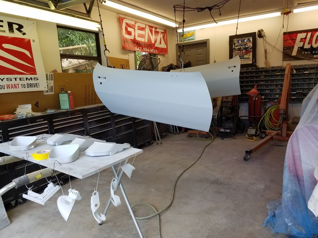
First, paint jail. I've been working on getting the 50 or so smaller pieces as well as the doors, fenders, trunk etc. into final sealer. Only have the body and hood left to block & seal. There's been no big rush to get everything cut in and assembled for paint because I needed to be able to use the sub frame and related parts for mocking up parts for the new company.

Lab-14 (short for Laboratory Fourteen) is my new endeavor. The initial products are low tech, simple things that are used to repair and/or strengthen, the 2nd gen platform. Products for first gens and other platforms will be developed as the company moves forward. Some of the products are items that showed up previously in this thread while others haven't been talked about here yet. I'll write a separate post about the new company and products and go into more detail about the individual parts.

PTFB is now sponsoring the car and so all the old suspension components from various manufacturers are being replaced with PTFB GEN II products. The car will remain a traditional coil/leaf spring car (my decision) and will certainly be a challenge to get set up and tuned with the additional down force created by all the aero modifications I've been making. Since I work building cars for others also, I sold everything that came off of my car to a customer with a 70 TA who wanted them all installed. In addition to the springs, sways, control arms, shocks etc. that came off of my car I also replaced the steering with new pieces from PTFB including an 800 12:1 box, tie rods and adjusters, Idler arm, ball joints including tall uppers, as well as the PTFB solid body mounts and GEN II frame connectors.

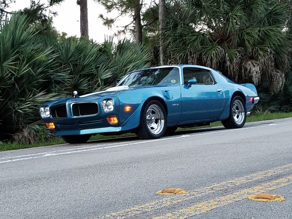
Well, everyone likes pics, so here's a couple of mine and one of the TA that now sports some of my old parts and a bunch of new PTFB goodies.

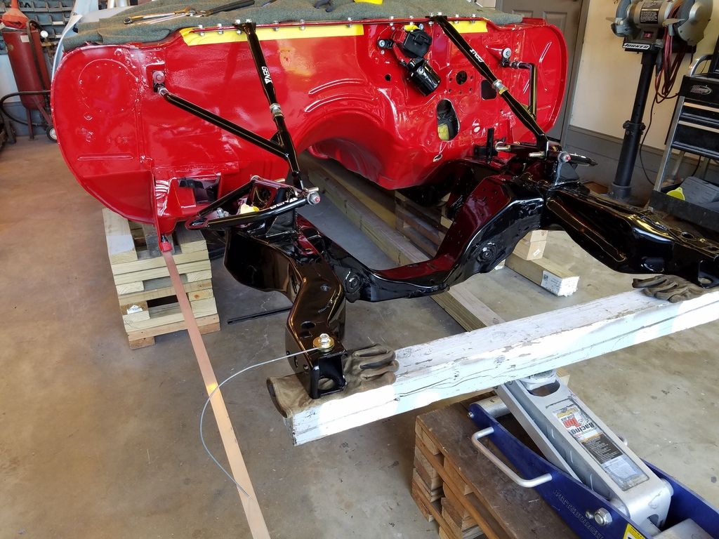
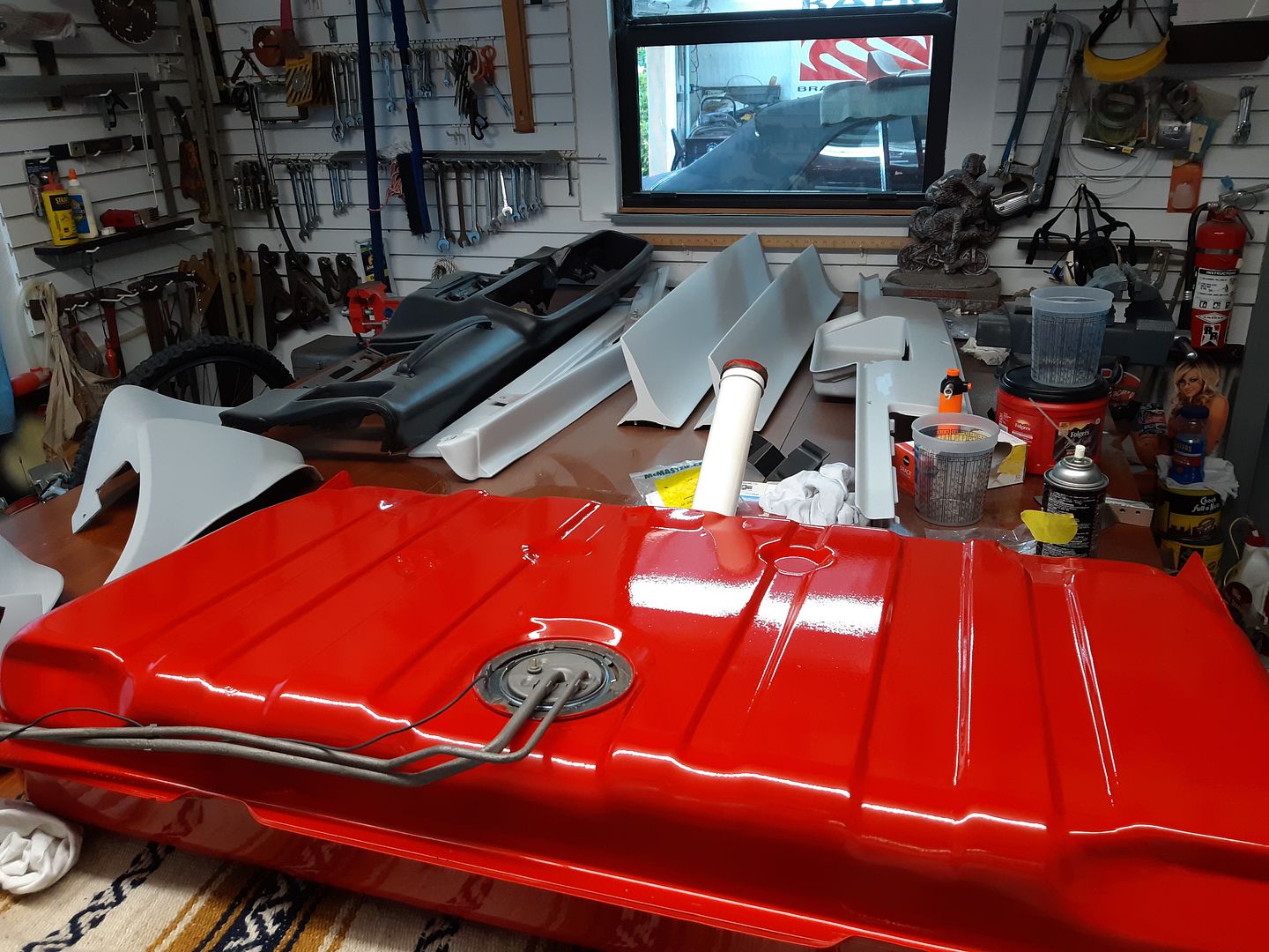
Digging my way out of paint jail a few pieces at a time.

[URL=http://s240.photobucket.com/user/NOTATA/media/The%2014%20Car%20Performance%20Therapy/20160531_140208_zpslvvccr9h.jpg.html][/URL]

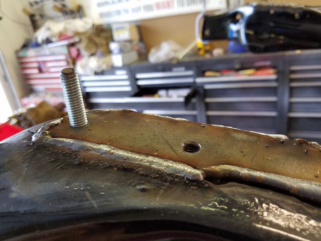
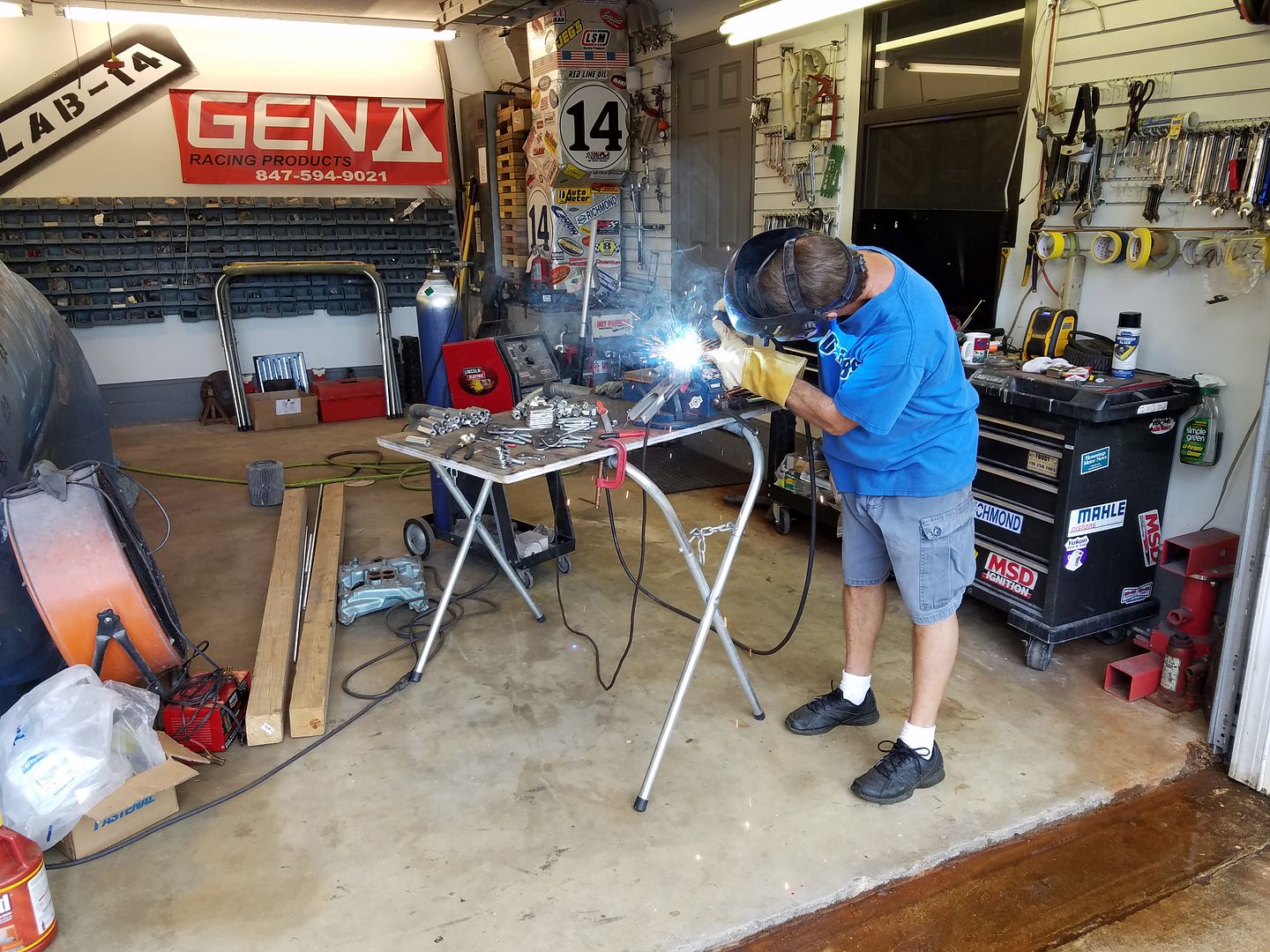
Installing Lab-14 front sway bar mounts. Will talk about them in an upcoming post.

[URL=http://s240.photobucket.com/user/NOTATA/media/The%2014%20Car%20Performance%20Therapy/20160524_161508_zpsxi3rfxfe.jpg.html][/URL]

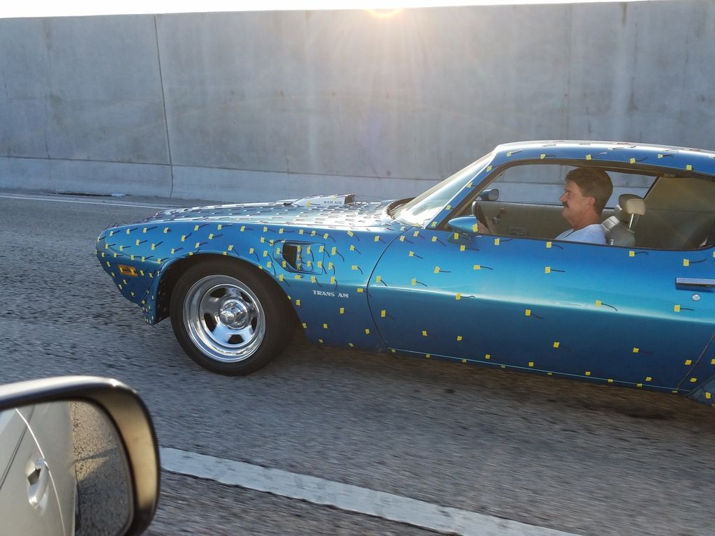
70 TA with a new attitude influenced by a lower altitude. You may notice the white ball looking thing on the hood. It's a Samsung 360 degree 3D virtual reality camera. An amazing piece of equipment that's supposed to be released in the USA in the next few days. I've had one at my disposal the past couple months and it's amazing. If you try one you'll be hooked. It's going to affect video as much or more than Go Pro's did. http://www.samsung.com/us/explore/gear-vr/?cid=ppc-

[URL=http://s240.photobucket.com/user/NOTATA/media/pauls%20TA/20160814_200055_zpspqzdx90m.jpg.html][/URL]

Dusterbd13
Dusterbd13 PowerDork
8/18/16 1:50 p.m.

What wheels are on that 70?

NOT A TA
NOT A TA Dork
8/18/16 8:45 p.m.

They're 17" chrome plated steel wheels. Center caps say Pacer.

SilverFleet
SilverFleet UberDork
8/19/16 8:07 a.m.

I can't wait to see the install on the PTFB stuff. I've been eyeing a few of their products over the years.

NOT A TA
NOT A TA Dork
8/19/16 10:12 a.m.
SilverFleet wrote: I can't wait to see the install on the PTFB stuff. I've been eyeing a few of their products over the years.

Before PTFB decided to sponsor my car I'd already started buying their parts. As a frugal GRM kinda guy I liked the products because they're designed well (updated geometry etc.), Made in the USA, and sell for reasonable prices. In my opinion, A lot of companies making suspension parts for 2nd gen F bodies have gotten carried away trying to outdo each other with the latest suspension technology. This has led to very expensive suspensions where the bang for the buck gets less and less while the installations and adjustments necessary to make them perform well has gotten more and more complicated.

One thing that PTFB products lack is good instructions. So I'm writing some for several of the components I'm installing that are aimed at the DIY guy who probably never installed similar pieces before. Hopefully they'll make it a lot easier for the novice DIY guy by noting tools they'll need and procedures while also giving tips to more advanced DIY guys and regular installers in shops that might save them a little time.

Since I installed a set of PTFB GEN II frame connectors on the blue car I wrote instructions. They can be bolted or welded on. Bolting is more difficult and time consuming and since the customer with the blue car needs them bolted for now to allow easy removal for under side restoration at a future date it was a good opportunity to write some instructions. I'll copy and paste them here so if you ever need them they'll be easy to find.

........................................................................................................

PTFB GEN II frame connector install, bolt in installation on 2nd gen F body.

Unless you're welding in the connectors they're more time consuming to install than say installing body mount bushings (as long as the body mount job goes smoothly). The average DIY guy can do this job over a weekend and the more advanced DIY guys can get it done in a day. Of course the amount of time necessary depends on several factors like whether you're using a lift of some type, floor jacks, wheel cribs, etc. and what tools you have available. There's more than one acceptable way of doing most jobs, and this is just my way of installing the PTFB GEN II connectors on this particular car as a bolt on application.

Before getting into the actual project let me review a few things concerning sub frame connectors.

First is the misconception that frame connectors eliminate flex. They do not, eliminate is a finite word, however they do greatly reduce the overall flex of the F body platform allowing the steering and suspension to act more precisely for better ride and handling. Also, by stiffening up the platform they can help reduce creaking, groaning, and other weird noises by more solidly connecting the front and rear of the car and reducing flex of the unibody, particularly the floor pan and the roof of T-top cars. Connectors also help provide better weight transfer to the rear wheels for those cars used at the drag strips.

When installing frame connectors, solid body mount bushings (preferred) or Urethane bushings should be used for bolt in applications and stock style rubber should not be used at all. If welding in the connectors (even if only on one end) only solid body mount bushings should be used.

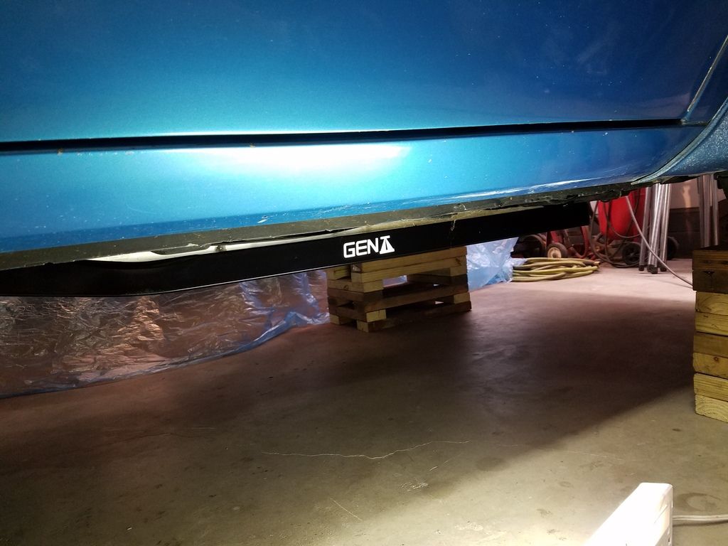
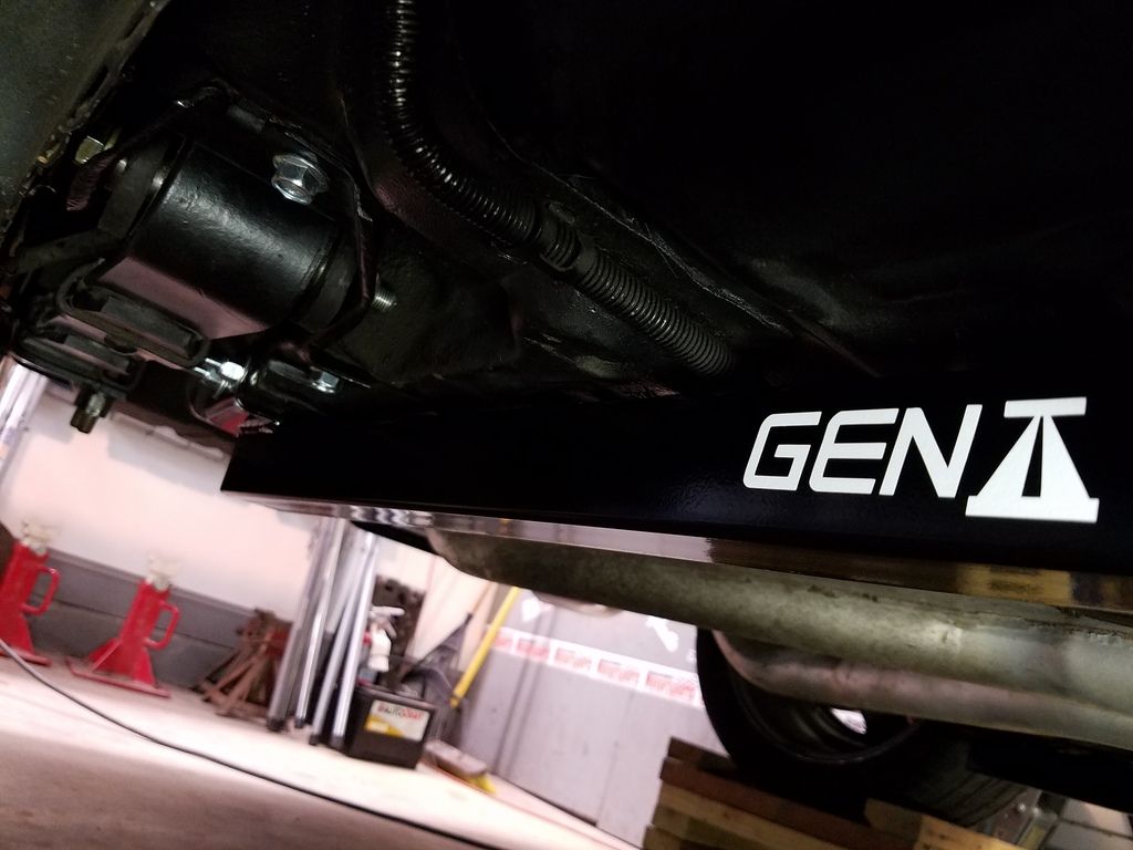
Most sub frame connectors reduce ground clearance from a stock vehicle. The PTFB ones shown here are 1/2" lower than the engine cross member when measured from the floor without driver etc. The springs, tire diameters, payload etc. will vary the ground clearance also so every car will be different. The connector is approximately 1-1/2" lower than the sub frame, so with that info you can figure out if the connectors will be lower than whatever exhaust or other low hanging things you may already have to determine if you'll loose clearance for speed bumps.

So on to the install!

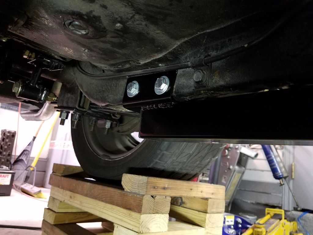
The first thing I do (when installing on an assembled car) is get the car up high enough to work on with the car in it's natural state. While the installation can be accomplished with the car up on several sets of jack stands, I like to have the car sitting as it would on the ground so I use wheel cribs. This keeps hanging weight of wheels, suspension, rear axle, etc. from distorting the sub frame or unibody which could cause preload when the car is returned to the ground. There's no need to compensate for the pitch of a normal garage floor. If you're working on a really uneven floor surface try to get the car level before installation. I'm not a big guy so some of you might want to raise the car a little higher than I have shown, just count the wheel cribs.

[URL=http://s240.photobucket.com/user/NOTATA/media/pauls%20TA/20160727_134654_zpsn6uksti4.jpg.html][/URL]
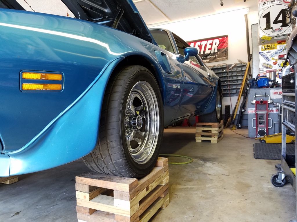
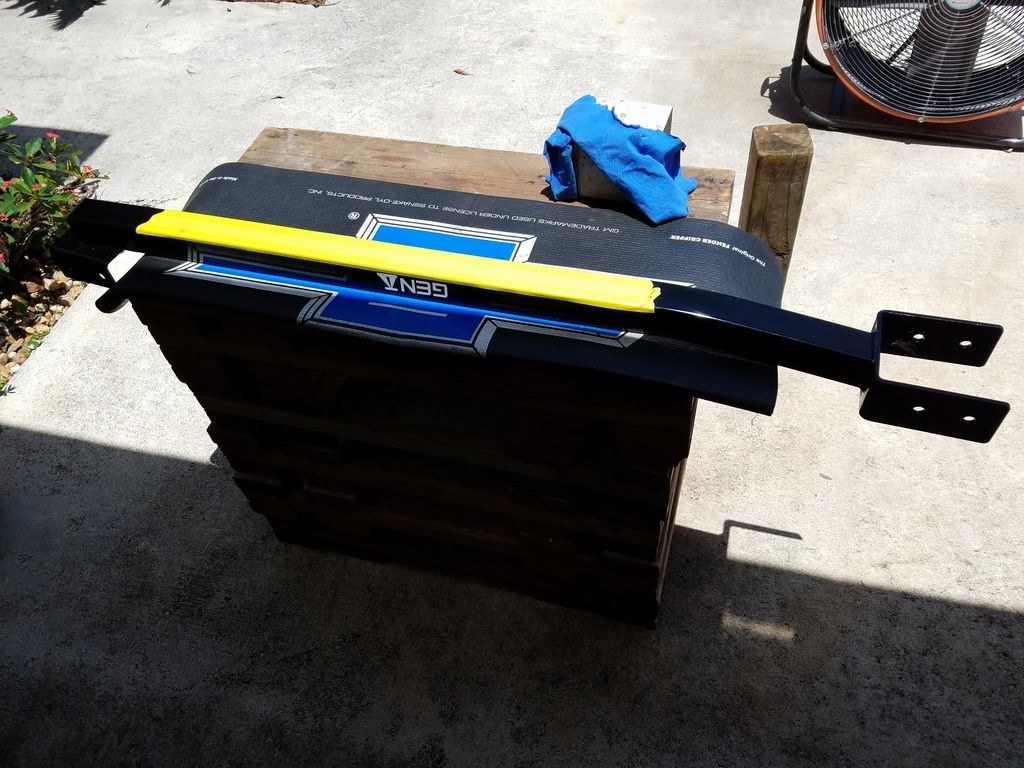
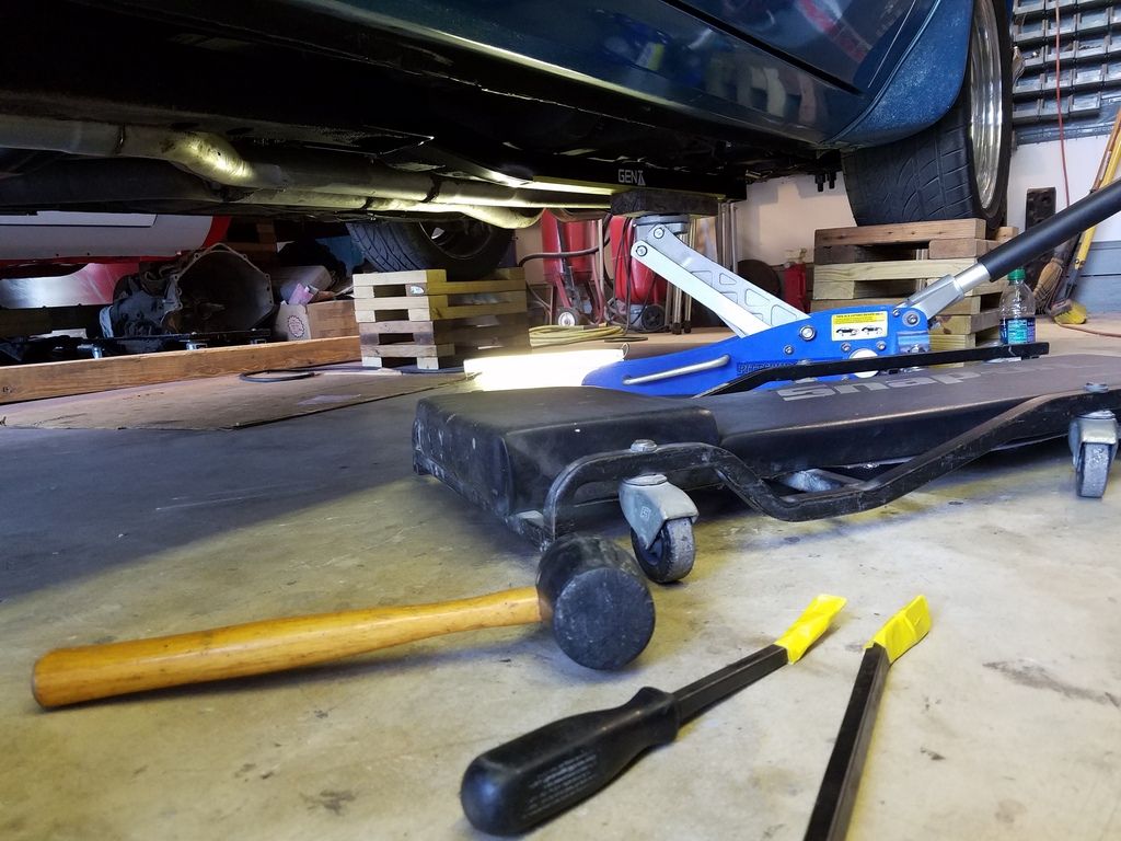
To prevent making any marks or scratches on the connectors during installation I use masking tape where they'll be held up to the car, then a block of wood on a floor jack to lift it up into place. Some persuasion with a rubber hammer and/or tape covered pry bars coaxes the connector into position without marking it up. On the drivers side you'll want to be careful of the parking brake cable to avoid pinching it against the floor or causing something that can rattle later on. On the passengers side you'll need to remove some brackets to get the fuel lines out of your way. Raise the connector but do not push the connector up until it hits the floor pan trying to maximize ground clearance or you'll create a place where the floor might creak or squeak by rubbing on the connector. Leave 1/8"-1/4" clearance to the floor pan. Keep in mind the front of the connector mounts using 4 short 3/8" bolts and 2 long 3/8" bolts are used through the rear frame rail. All bolt heads and nuts will have a washer under them.

[URL=http://s240.photobucket.com/user/NOTATA/media/pauls%20TA/20160727_141108_zpsauxlrbyx.jpg.html][/URL]
[URL=http://s240.photobucket.com/user/NOTATA/media/pauls%20TA/20160727_142214_zpsr28yusep.jpg.html][/URL]
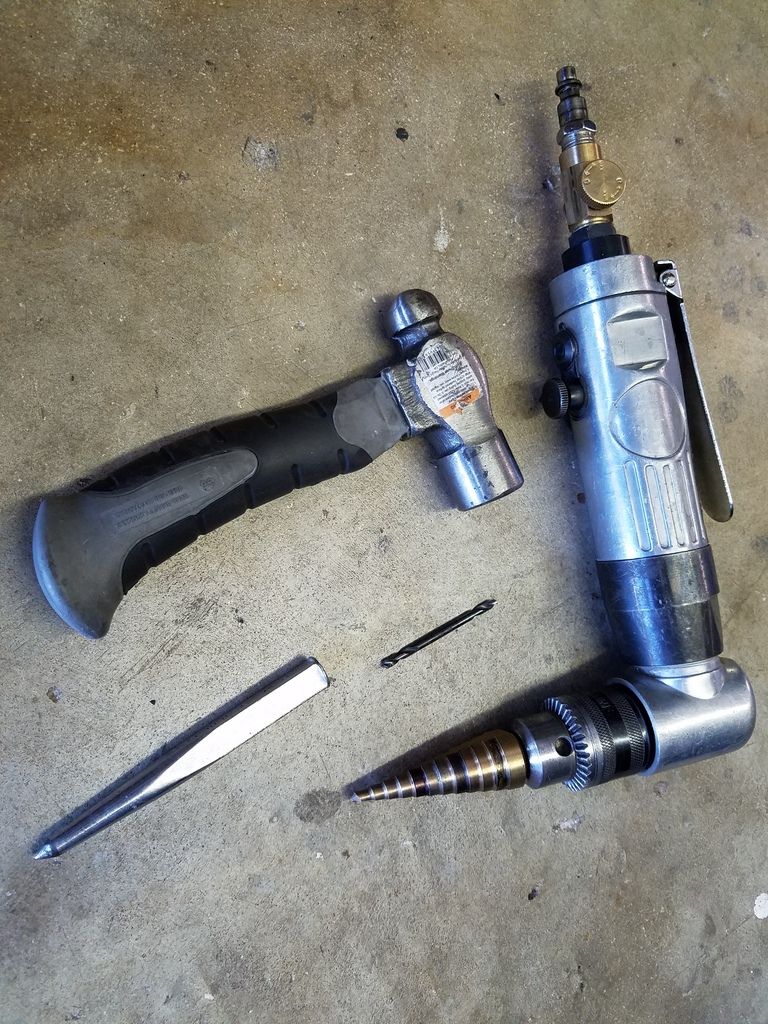
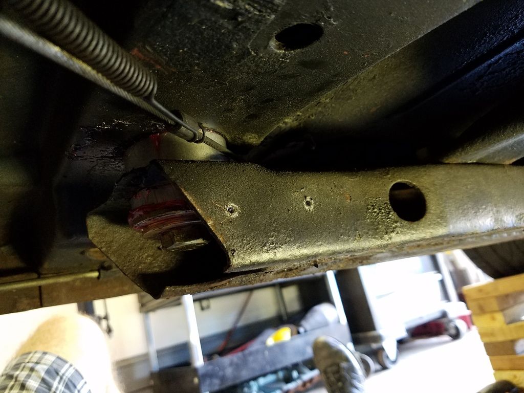
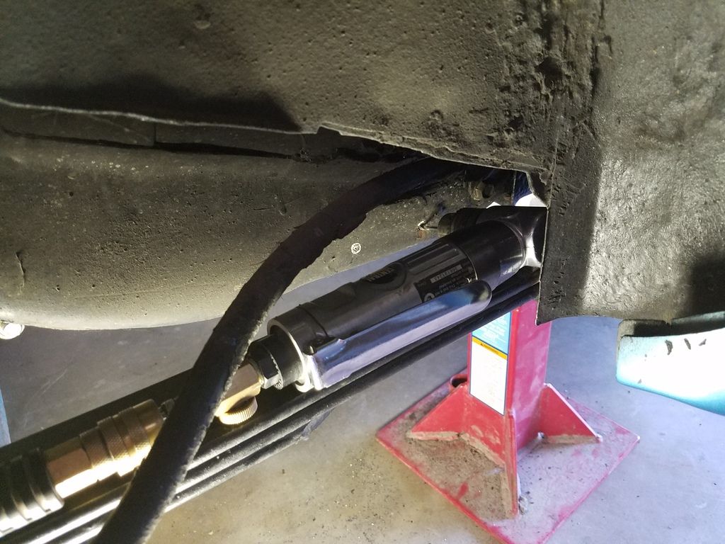
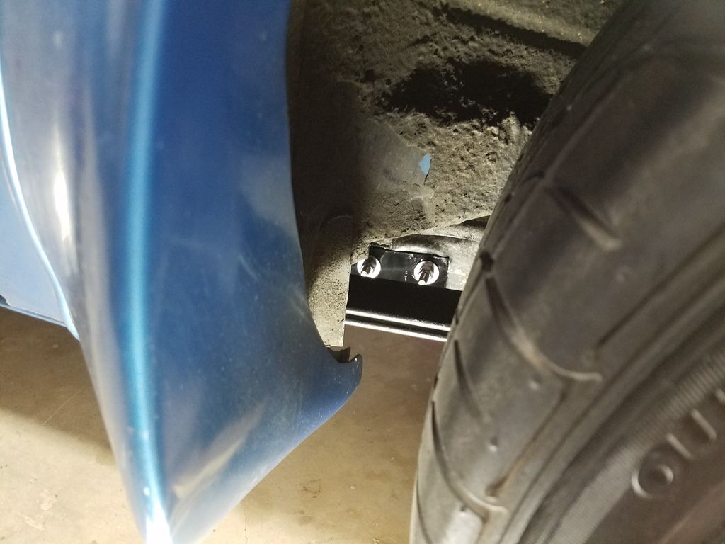
Once you have a connector in position use a grease pencil or piece of chalk to mark all of the holes on the inside and outside of the sub frame and rear frame rail where bolt holes need to be drilled. Lower the frame connector and set aside. I keep a piece of cardboard under the car to put them on so I don't chip, scratch, etc. Next center punch each of the bolt hole marks so you can get a drill bit started without it walking sideways on you. I drill all the holes out with an 1/8" bit before drilling out to a larger size then open them all up to 3/8". You can NOT drill through the rear frame rail to drill the outside holes because the holes in the bracket on the connector don't line up inside/outside exactly. You must drill 4 different holes in the rear frame. Yes, drilling the outside holes is a pain because of limited access in the fender well and spring interference where you need to place the drill. You may have to support the unibody and lower the rear axle to get clearance for a drill by the rear spring as seen in pics below. Once you've got the 4 holes in the rear frame rail put a long 3/8" bit in the drill and run the drill bit all the way through to the corresponding outside hole by the spring. This will make life a lot easier when trying to get the long bolts through later on.

[URL=http://s240.photobucket.com/user/NOTATA/media/pauls%20TA/20160727_153348_zpspeoccsbh.jpg.html][/URL]
[URL=http://s240.photobucket.com/user/NOTATA/media/pauls%20TA/20160727_153118_zpsq4wpevtg.jpg.html][/URL]
[URL=http://s240.photobucket.com/user/NOTATA/media/pauls%20TA/20160727_190829_zpsuqdfh6rf.jpg.html][/URL]
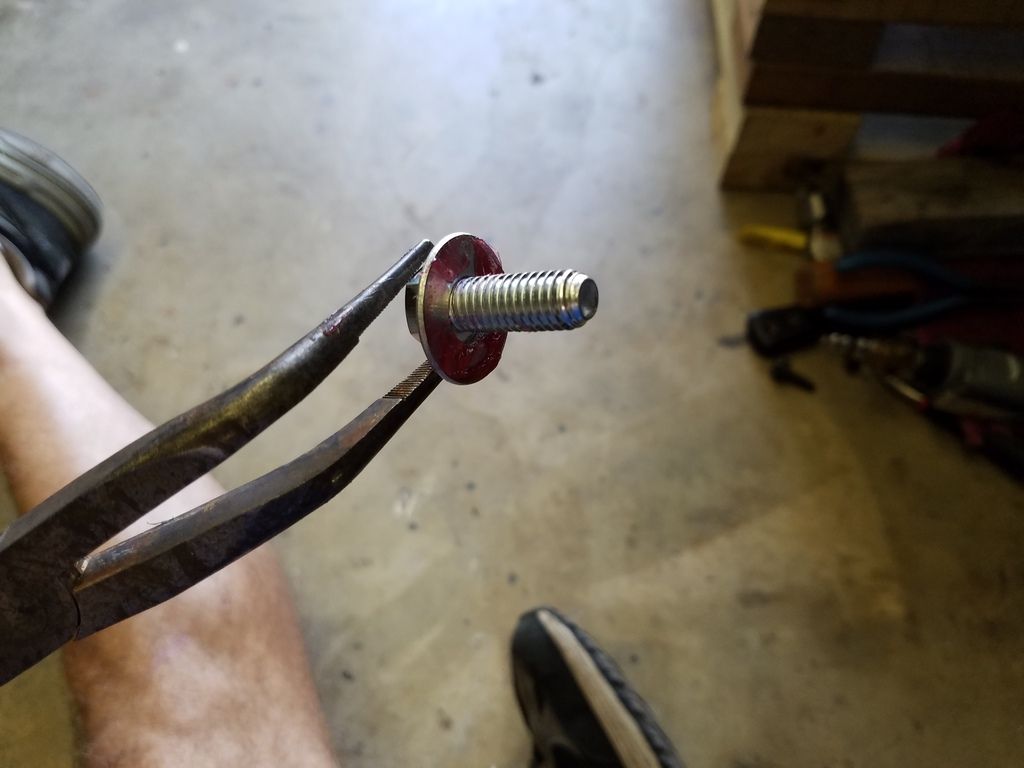
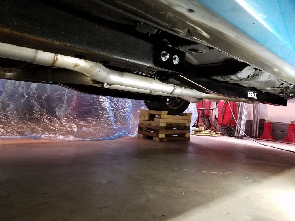
Once all the holes are drilled, grease the inside of the frame connector brackets where they will contact the sub frame and rear frame rail. This helps prevent creaking or squeaking later on. Lift the frame connector into position (without a jack) and just stick one bolt in the front and rear to hold it up. Then, one by one, loosely install each of the bolts with grease on the washers where the washers will contact the connector, inside of sub frame or rear frame rail. You may need to use a round file or your drill to open up some of the holes a little bit depending on how well you marked and drilled your holes. On an early 2nd gen the body mount bushing is in the way installing the front bolts. To make things easier install the farthest forward bolts from the inside of the frame with a pair of needle nose pliers as seen in pic and the ones right next to the body mount pointing inward. Later framed cars have more bolt access so your choice.Once you have all the bolts in place snug them all up before torquing. Dave at PTFB says you can go up to 30 lbs on the front since it's grade 5 hardware. I'm not going to recommend a particular torque for the long rear bolts which are also grade 5 hardware just be careful not to crush your rear frame rail.

[URL=http://s240.photobucket.com/user/NOTATA/media/pauls%20TA/20160728_131019_zpsedzondyw.jpg.html][/URL]
[URL=http://s240.photobucket.com/user/NOTATA/media/pauls%20TA/20160728_193435_zpsdxni52nv.jpg.html][/URL]
[URL=http://s240.photobucket.com/user/NOTATA/media/pauls%20TA/20160728_203157_zpsyqjwhrt9.jpg.html][/URL]
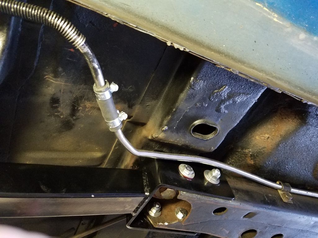
Once your connectors are mounted you'll need to make some minor alterations to the fuel lines and move a bracket on the outside of the passenger side sub frame to a location a little forward by drilling a couple new holes. Be sure the fuel line is not going to rub on a bolt head or sharp corner of the connectors. Here's a few misc. pics for those who might want to see certain things.

[URL=http://s240.photobucket.com/user/NOTATA/media/pauls%20TA/20160728_203512_zps4fl51sqg.jpg.html][/URL]
[URL=http://s240.photobucket.com/user/NOTATA/media/pauls%20TA/20160728_203256_zpspqrqu9t3.jpg.html][/URL]
[URL=http://s240.photobucket.com/user/NOTATA/media/pauls%20TA/20160728_203411_zpskvg1qsnu.jpg.html][/URL]
[URL=http://s240.photobucket.com/user/NOTATA/media/pauls%20TA/20160728_203525_zpschwxy3hk.jpg.html][/URL]
NOT A TA
NOT A TA Dork
10/31/16 5:39 p.m.

This is my shameless self promotion post about Laboratory Fourteen "Lab-14", a company I started earlier this year. There's no budget for advertising yet so I can't sponsor any of the forums this thread is posted on so if a mod feels this post isn't appropriate or it conflicts with forum rules just delete it and I won't be offended. I'll get back to the regular project posts after this one.

As mentioned previously I started a new company named Laboratory Fourteen "Lab-14" based primarily on parts to repair and reinforce the 2nd gen F body sub frame and also including some restoration reproduction pieces. I 'd been making "one of" pieces for repairs and builds on other peoples cars and mentioned the pieces I'd made for my car in this project thread (which is on several forums) asking if anyone else wanted them. After selling through PM's and emails for a while making small batches of products I figured I should just form a legal business and expand the product line. I've owned several successful businesses I built from scratch and operated for as long as 25 years before moving South, so I've got some experience. The concept of Lab-14 is simple products based on repairing and reinforcing factory chassis to provide a solid footing for all the modern suspension and tire technology we have available today. To make this concept work I realized it's gotta be cheaper, easier, and quicker to just buy my products than to try and copy them yourselves.

Thanks to all of you who went through PM's and emailing back and forth to purchase products before I finally got the onlne store set up. Here's a link to the store for anyone interested in checking out the products. https://www.lab-14.com/ Most products are for the sub frames and some are G-brace accessories but there's also some restoration sheet metal pieces that have not been reproduced till now.

By offering a number of different things that can all be purchased from one place a person can get everything to beef up a sub frame designed to work together from Lab-14 with just one shipping charge. Saves time driving around buying materials and hardware then trying to find items not available locally online. It's easier because the material choices, pattern making, and metal fabrication work is done, plus all the correct hardware has been figured out and included. You can just order everything in one shot from the online store at WWW.lab-14.com rather than trying to make your own stuff buying metal from here or there then fabricating etc.. and figuring out what hardware is needed then purchasing from multiple places. It's cheaper because you're not spending money driving around trying to source materials and hardware, paying shipping from multiple vendors, and buying materials and hardware you don't need because you can only buy in quantities greater than what is actually needed. After all, most people want to just build the car not spend all their time fabricating, sourcing, etc. It takes long enough to complete projects already.

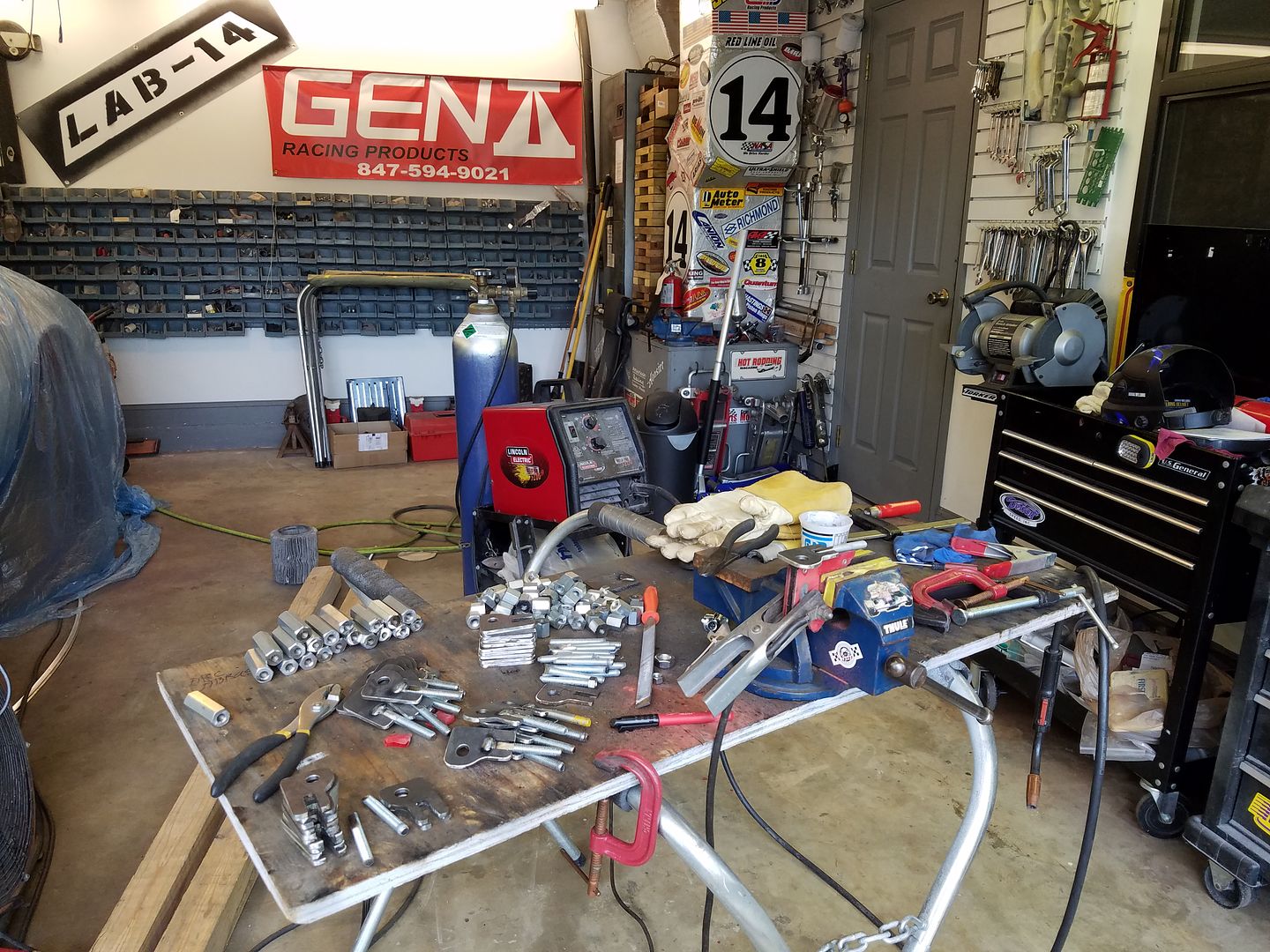
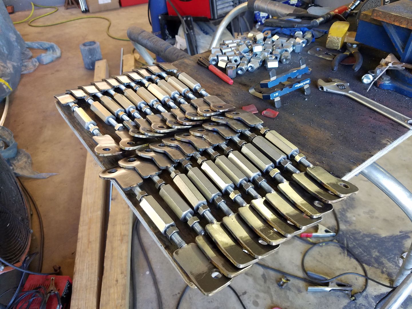
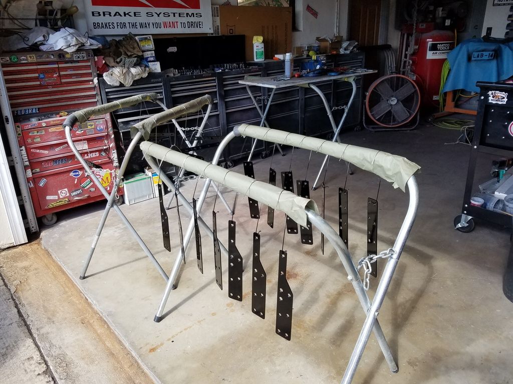
Since we all like pics, here's a couple pics of products taken during small batch production to get the company going.

[URL=http://s240.photobucket.com/user/NOTATA/media/Lab%2014%20products/20160911_171109_zpsghev3d22.jpg.html][/URL]

[URL=http://s240.photobucket.com/user/NOTATA/media/Lab%2014%20products/20160911_171551_zpsgoirbyns.jpg.html][/URL]

[URL=http://s240.photobucket.com/user/NOTATA/media/Lab%2014%20products/20160914_160437_zps6zm1rksw.jpg.html][/URL]

[URL=http://s240.photobucket.com/user/NOTATA/media/Lab%2014%20products/20160712_094832_zpsfg34sloa.jpg.html][/URL]

NOT A TA
NOT A TA Dork
1/24/17 2:03 p.m.

During the past couple months I haven't worked on the Firebird itself as much as I'd have liked to. I've been busy with the Lab-14 stuff and got involved in replacing the trunk pan, trunk drop offs, inner splash pan, frame rails, and torque boxes in my 67 Camaro that started with the intention of a much smaller project replacing the rear springs. However I did do some deflection testing of the 2nd gen sub frame using various parts from PTFB and Lab-14. I also did some baseline tuft testing on the highway for aerodynamics using a customers car with the same body, ride height etc. as my car (with the owners permission of course).

Pic below was taken during deflection testing. The front foot wells and cowl area were filled with a few hundred lbs of weight while the body was supported on wood cribs. A piece of right angle was bolted to the pinch weld on the body and an indicator bolted to the front of the frame horn to note deflection. Solid body mounts were used and I've boxed the rear body mount area of the subframe. I could get almost 3/4" vertical deflection of the sub frame alone when using a floor jack to apply pressure straight up under the frame horns until the body started to lift off the wood cribs. Not sure if more weight in the body would allow even more deflection but I was surprised to see how much frame deflection there was. I would expect similar deflection in the opposite direction would be possible and may test for that when I do some torsional testing. With a combination of the PTFB G-braces and Lab-14 parts vertical deflection was reduced to less than 1/8 " which appeared to be caused by the deflection of the floor pan where the rear body mounts on the sub frame attach under the front seats.

[URL=http://s240.photobucket.com/user/NOTATA/media/Lab%2014%20products/20160622_183527_zpsjgrgdr4x.jpg.html][/URL]

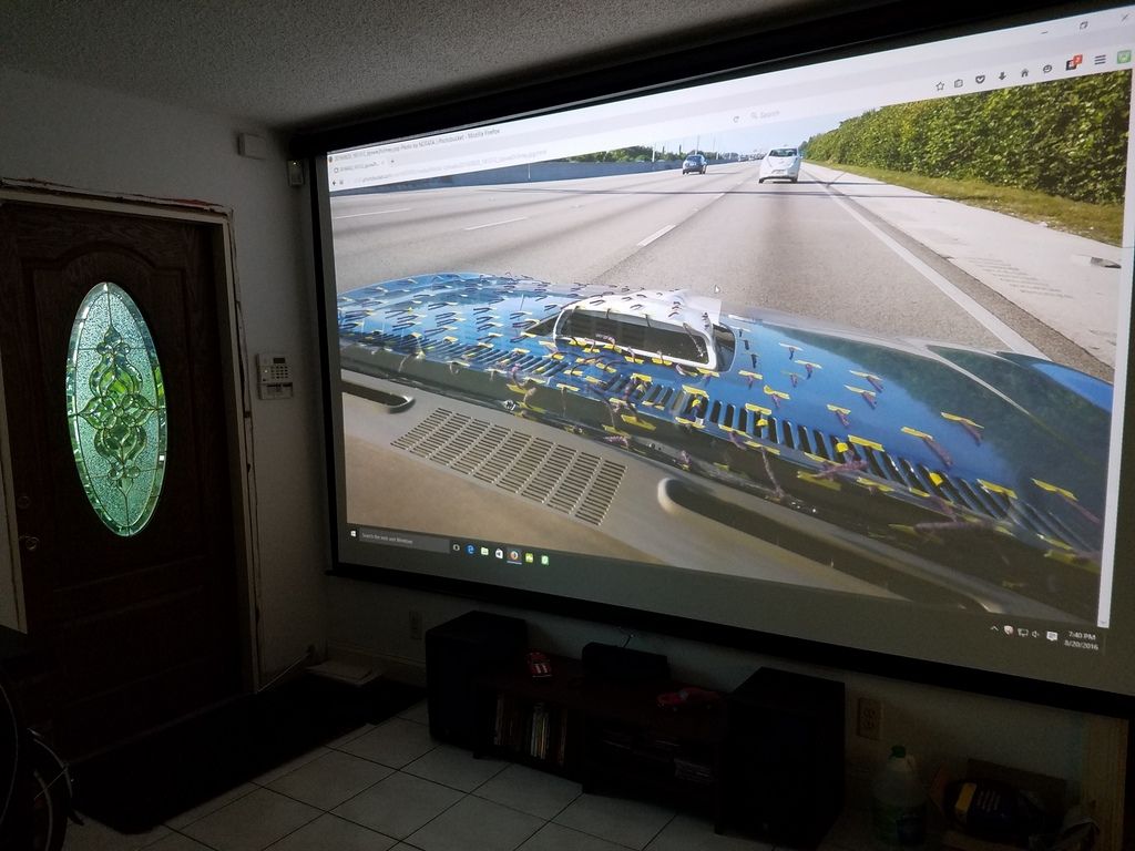
The availability of a car with the same body, ride height, and tire size as a baseline test mule prompted me to do some tuft testing at highway speeds to get a good look at whats going on with the stock body configuration I started this project with. I'll do similar testing after my car's back on the road to see if I can note any differences due to all the aero changes and modifications. I'll post a couple still pics here and if anyone's interested there's some 360 degree VR videos we made I'll put links for . Those with certain phones or other devices may be able to pan around 360 but you'll need a headset to see full 360 3D VR. Sound is mostly wind noise since the 360 camera was out on a stick held out the window at 60-70 MPH so just turn it down. https://www.youtube.com/watch?v=6KQA9BzpN50 https://www.youtube.com/watch?v=h6pxo5eh7Zw

By being able to put the videos up on the big screen with the projector I can watch small areas or even individual tufts. So for those who always wondered if there is a ram air effect influencing the air for a 2nd gen TA shaker scoop created by the high pressure area at the base of the windshield, the answer is no at up to 70 MPH. I'll test that again with my own car at much higher speeds on track but I doubt there will be any noticeable air being forced into the scoop. If anything there's a possibility air may actually be getting pulled out at high speeds.

[URL=http://s240.photobucket.com/user/NOTATA/media/AERO/20160822_182558_zpslrtvi7sc.jpg.html][/URL]

[URL=http://s240.photobucket.com/user/NOTATA/media/AERO/20160822_182605_zpsfunvhaet.jpg.html][/URL]

[URL=http://s240.photobucket.com/user/NOTATA/media/AERO/20160820_194054_zpscm1tawj2.jpg.html][/URL]

NOT A TA
NOT A TA Dork
4/13/17 5:24 p.m.

I got side tracked on this Firebird project by working on my 67 Camaro. What started as a small project of replacing the rear springs and shocks quickly developed into cutting out the whole trunk floor, drop offs, frame rails, torque boxes etc. due to rust. I knew the back of the car would eventually need attention because of rust but once I started cutting out the old springs and found the torque boxes rusted out where the spring pockets bolt in I knew I was in much deeper than I wanted to be but reluctantly ordered new sheet metal.

While working on the Camaro as time between customer projects allowed I had a heart attack which stopped progress on both cars completely. Had an operation to install a couple stents in my heart and the docs said I better take it easy for a month to let the heart muscles heal. So the bad news is both car projects came to a temporary halt but the good news is I'm still alive and someone didn't have to come post about my demise in this thread. I've been expecting a heart attack due to my age and family history so it wasn't a surprise. I have older and younger cousins who've had up to 9 stents and others who had quadruple bypass surgery. No disruption to Lab-14 and no shipping delays. All items (including some new ones) are currently in stock www.lab-14.com

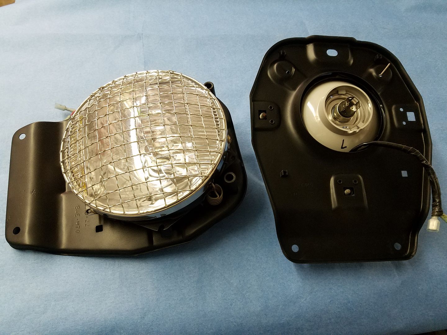
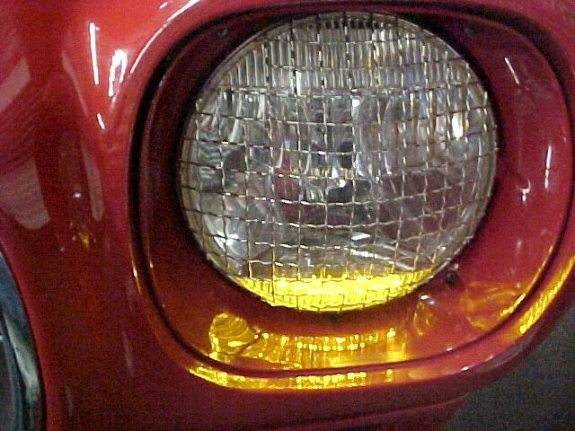
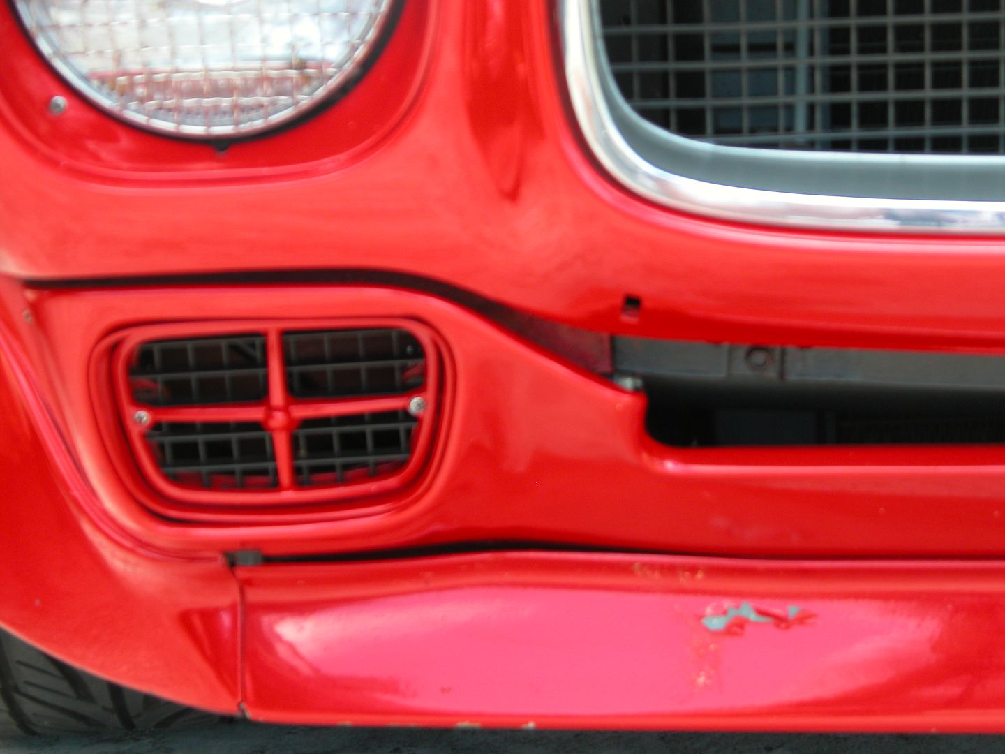
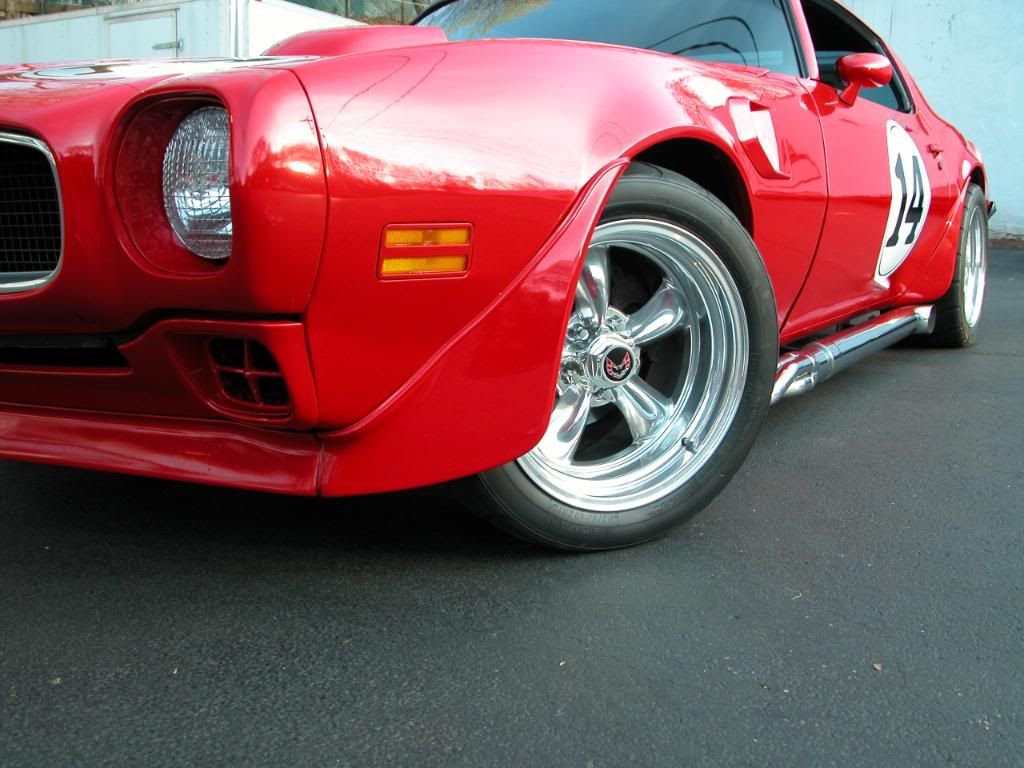
I did get a small project done for the Firebird before the heart attack I can share. I blasted and painted the headlight assembly parts which is kinda boring by itself if they're stock but since I have special headlights and protective screens they're a bit different and even if you saw pics of my car before I took it apart for this project you probably didn't see the light modifications so I'll share them now.

About 10 years ago I decided I wanted to use the front parking light/turn signal openings for brake ducts. So I bought some plastic halogen headlights with built in LED park/turn lights from a hot rod supplier. This was back before all the crazy headlight options we have now. The lights themselves required modifying the headlight mounts and wiring, they're not a simple swap. I also wanted to avoid having to put blue tape over my headlights for road track days as required by some tracks and like the look of screens. So I bought some stainless headlight screens made for off road Jeeps and modified them so I could use them on my bird. Then I cut pieces out of some extra stock grills to use in the park/turn openings so they'd appear kinda factory looking.

[URL=http://s240.photobucket.com/user/NOTATA/media/The%2014%20Car%20Performance%20Therapy/20170129_181640_zpsexsgrpxd.jpg.html][/URL]

[URL=http://s240.photobucket.com/user/NOTATA/media/Firebird/MVC-015F-1.jpg.html][/URL]

[URL=http://s240.photobucket.com/user/NOTATA/media/026.jpg.html][/URL]

[URL=http://s240.photobucket.com/user/NOTATA/media/RAD%20CAPZ%20Wheel%20Nutz/WheelNutzonThe14Carshoot1014.jpg.html][/URL]

wheelsmithy
wheelsmithy GRM+ Memberand Dork
4/13/17 5:38 p.m.

Glad you are still with us. Great work, as always.

SEADave
SEADave HalfDork
4/13/17 6:58 p.m.

Glad to hear you are ok, hope you are feeling better. Still great work as always, and an inspiration for my own '78 Esprit project. The Esprit has actually been sidetracked by my '81 LG4/WS6 TA which I've now decided to use for an E-Rod LS3 project. Wish you weren't as far away as possible in the lower 48 because I sure could use your help on both projects!

EastCoastMojo
EastCoastMojo GRM+ Memberand Mod Squad
4/13/17 8:41 p.m.

Dang dude, glad you came though ok. Loving your build!

NOT A TA
NOT A TA Dork
4/14/17 10:41 a.m.

Thanks folks! Dave, the E-Rod LS 3 is one of the best things that could happen to an 81 TA.

Dirtydog
Dirtydog GRM+ Memberand New Reader
4/14/17 1:06 p.m.

Glad to see you back in action. As Mickey Mantle once said "If I knew I was going to live this long, I would have taken better care of myself." I occasionally follow your work on another web site. You do impressive stuff, keep it up.

NOT A TA
NOT A TA Dork
7/4/17 10:33 a.m.
Dirtydog wrote: Glad to see you back in action. As Mickey Mantle once said "If I knew I was going to live this long, I would have taken better care of myself." I occasionally follow your work on another web site. You do impressive stuff, keep it up.

I fall right into Mickey's situation. Lots of deferred maintenance due to lack of any medical insurance and the expectation that I'd have a heart attack late 50's early 60's that would kill me like my ancestors. Been a rough few months with post surgery complications but I'm getting back at things.

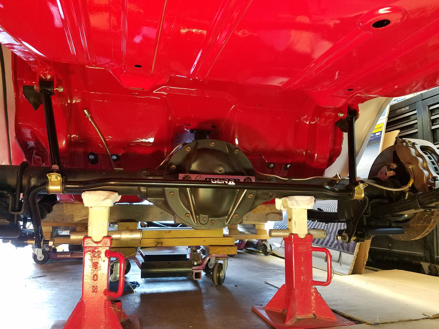
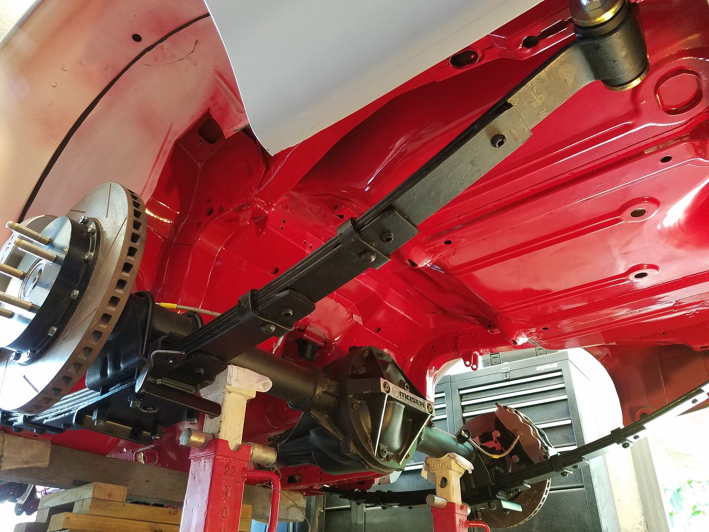
Installed the rear suspension in the Firebird last weekend but don't want to write an extensive post with lots of pics knowing they may all be gone due to the new photobucket pricing structure. I've had an account but not going to pay $400.00 for third party hosting. It still seems to work now so I'll try a couple pics. Funny thing is, photobucket is working faster for me with no pop ups than it has in over a month and I'm only on a Plus 20 account so I'm not supposed to have 3rd party hosting anymore.

[URL=http://s240.photobucket.com/user/NOTATA/media/The%2014%20Car%20Performance%20Therapy/20170629_181229_zpsyf4u5im2.jpg.html][/URL]

[URL=http://s240.photobucket.com/user/NOTATA/media/The%2014%20Car%20Performance%20Therapy/20170626_131614_zpszjiqhpcy.jpg.html][/URL]

conesare2seconds
conesare2seconds Dork
7/4/17 1:26 p.m.

Car is looking good, glad you're doing better too.

AngryCorvair
AngryCorvair GRM+ Memberand MegaDork
11/18/19 12:30 p.m.

resurrecting a zombie thread to find out if there are any updates to report?

NOT A TA
NOT A TA SuperDork
11/26/19 11:31 a.m.
AngryCorvair said:

resurrecting a zombie thread to find out if there are any updates to report?

Yes there are updates and I need to spend some time one evening and post about them. Progress has been very slow the past couple years due to medical issues and their cost and then progress got slowed down even more recently when I accidentally poisoned myself and came very close to dying again.

AngryCorvair
AngryCorvair GRM+ Memberand MegaDork
11/26/19 5:32 p.m.

In reply to NOT A TA :

Please stop that!  You have too much to teach us still!

Cotton
Cotton PowerDork
11/26/19 6:39 p.m.

I love this car.  Hope things start looking up on the health front.

NOT A TA
NOT A TA SuperDork
5/24/20 3:04 p.m.

I wish I could say I've been getting healthier but that hasn't been the case.

Was hauled away by paramedics almost dead twice in the past 6 months. No explanation for the heart problems and had another round of angioplasty where they said everything looked good. Sometimes my heart rate has been as low as 35 BPM and body temp only 95. I've passed out and crashed onto things andthen hit the floor. Between the symptoms and what not it beats the heck out of me when it happens.  

Back muscles give me grief about 1/2 the days limiting what I can do (like today), and leftover Lyme disease ailments stop by for occasional visits with symptoms like making my hands hurt really bad for a week.

Meanwhile Prostrate and bladder ailments are slowly getting worse and depending on the day I may have to self catheterize up to three times a day with an 18" straw I have to shove up my hootus. Not fun at all to do when the back muscles barely let me walk never mind bend and shove the tube up . Getting old sucks.

But I'm still alive! So on to cool car stuff! Quoting myself so I save time before next the update which is below it.

NOT A TA said:

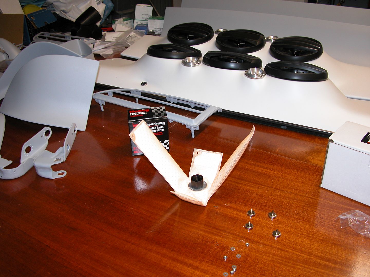
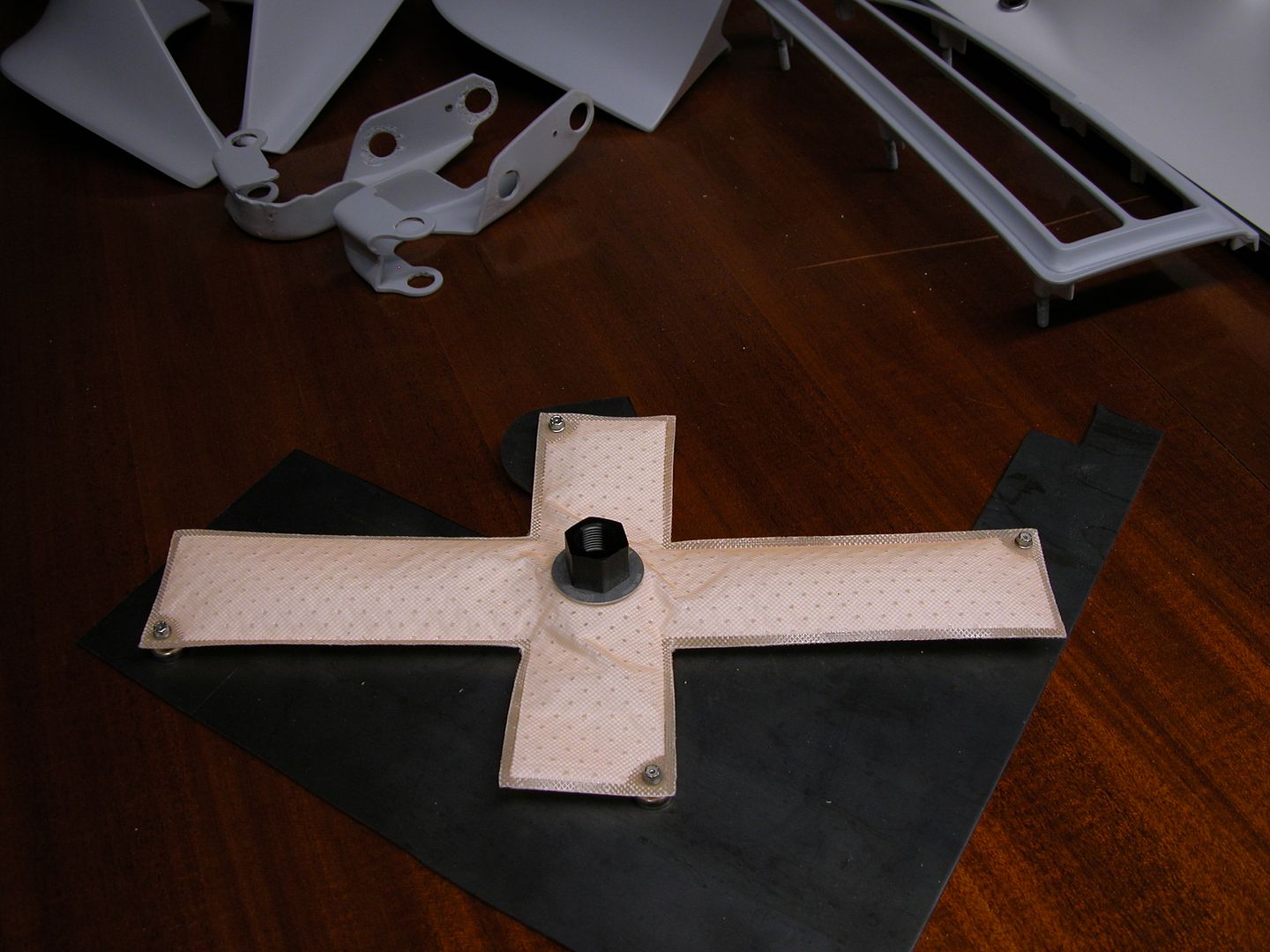
Back in the fall Holley introduced a new product at the SEMA show, the Holley Hydramat. It's a product that mounts in the bottom of a fuel tank and if the fuel in the tank touches any part of the Hydramat the fuel will be sucked in even if no gas is touching the rest of the hydramat. https://www.youtube.com/watch?v=yfE1v65fNZI

Holley started shipping about a month ago so I ordered one and got it a couple weeks ago so I thought I'd show it here. Will post about it again when I get it set up in the tank. Cost of mine was a couple hundred bucks. Seems expensive but to save the same weight (on track) with lightweight parts would cost more

This looked like a good product for me to try in my stock unbaffled gas tank until I can install a properly mounted and protected fuel cell. It'll allow me to save weight by keeping less fuel in the car on road courses without risking sucking air in high G corners, reduce the pendulum effect of fuel sloshing in the tank, be safer if there's a fire because less fuel in the car, and since it's also a filter I eliminate the canister fuel filter I've been using also saving weight.

I got the magnet kit for mounting the mat in the tank and will need to install submersible fuel line instead of the stock tube and sock strainer in the tank. Holley makes other sizes and shapes of the mat as well as types of mounting setups for tanks made out of other materials.

[URL=http://s240.photobucket.com/user/NOTATA/media/The%2014%20Car%20Performance%20Therapy/004_zpslhlre45z.jpg.html][/URL]

[URL=http://s240.photobucket.com/user/NOTATA/media/The%2014%20Car%20Performance%20Therapy/005_zpsu2wxawst.jpg.html][/URL]


_____________________________________________________________________________________________________________________


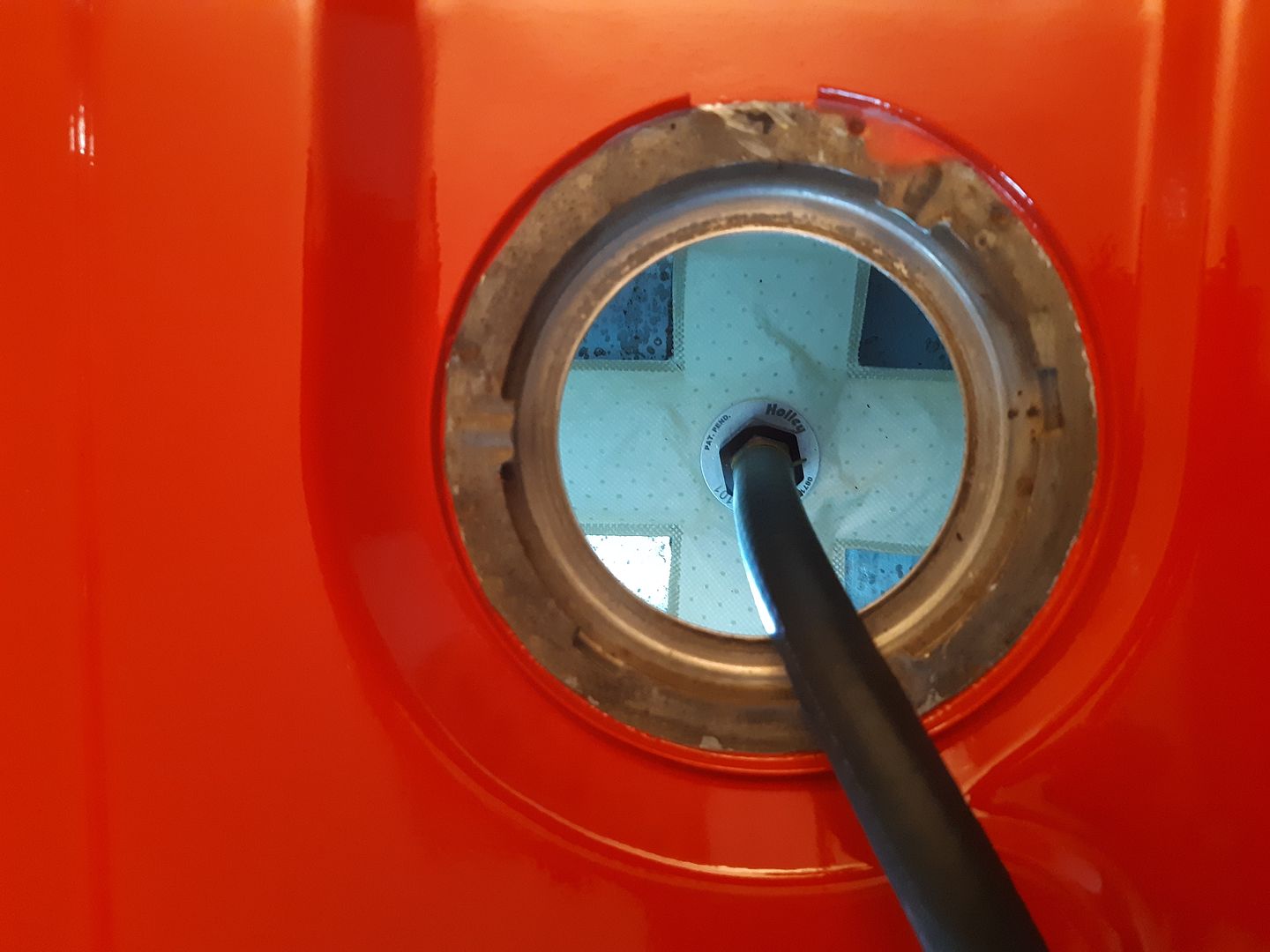
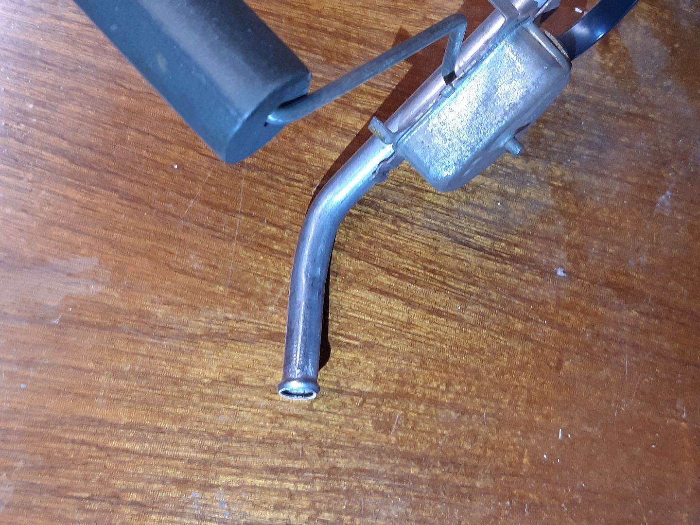
So 5 years after I bought the Holley Hydramat I finally installed it. I got a new gasket and ring from Rock Auto for the fuel sending unit. Sandblasted the fuel sending unit with the part that's normally in the tank protected by a thick plastic bag duct taped over the fuel float etc.   Then used an Ospho type product and painted the parts that aren't in the tank. I cut down the fuel line where the stock sock type fuel filter attaches and flared the end of the tube. Used submersible 3/8" fuel line with a couple spring clamps to hold the rubber hose. No need for worm drive clamps because there's no pressure just suction.

Tips:

Cut hose long enough to easily connect the hose to the fuel sending unit AFTER the Hydramat is placed in the tank.

Install hose to Hydramat and install hydramat and  with hose curved (and clamped) so it lines up with direction the fuel pickup is pointed.

Then install hose to fuel pickup unit and rotate hose so it doesn't try to tip/pull the Hydramat when lowered in for test fit. Once happy with hose clamp hose.

[URL=https://s240.photobucket.com/user/NOTATA/media/The%2014%20Car%20Performance%20Therapy%20part%202/20190805_184759_zps071gdlyx.jpg.html][/URL]

[URL=https://app.photobucket.com/u/NOTATA/a/ac949837-2452-4f6a-b3a7-1455f6a2f0b0/p/a334f55d-59fb-46e4-a126-e3da9d2c1424][/URL]

[URL=https://app.photobucket.com/u/NOTATA/a/ac949837-2452-4f6a-b3a7-1455f6a2f0b0/p/f5d4287b-03d6-4ef0-a2f1-ea2882968932][/URL]

NOT A TA
NOT A TA SuperDork
5/24/20 3:18 p.m.

Sorry folks, Photobucket having issues yesterday & today with new pics being displayed on forums yet all the previously posted pics appear. Hopefully they get it fixed soon.

EDIT: Pics in posts fixed.

AngryCorvair (Forum Supporter)
AngryCorvair (Forum Supporter) GRM+ Memberand MegaDork
5/24/20 4:31 p.m.

In reply to NOT A TA :

Glad to see this thread on page 1. Not glad to hear of all the ailments. *Very* glad you're a fighter! 

jfryjfry (Forum Supporter)
jfryjfry (Forum Supporter) Dork
5/24/20 7:34 p.m.

Wow, so sorry to hear all that you're dealing with.  You sure seem to have a great attitude about it and dealing with it quite well. 
 

hope the cars progress quickly!

NOT A TA
NOT A TA SuperDork
6/1/20 11:59 a.m.

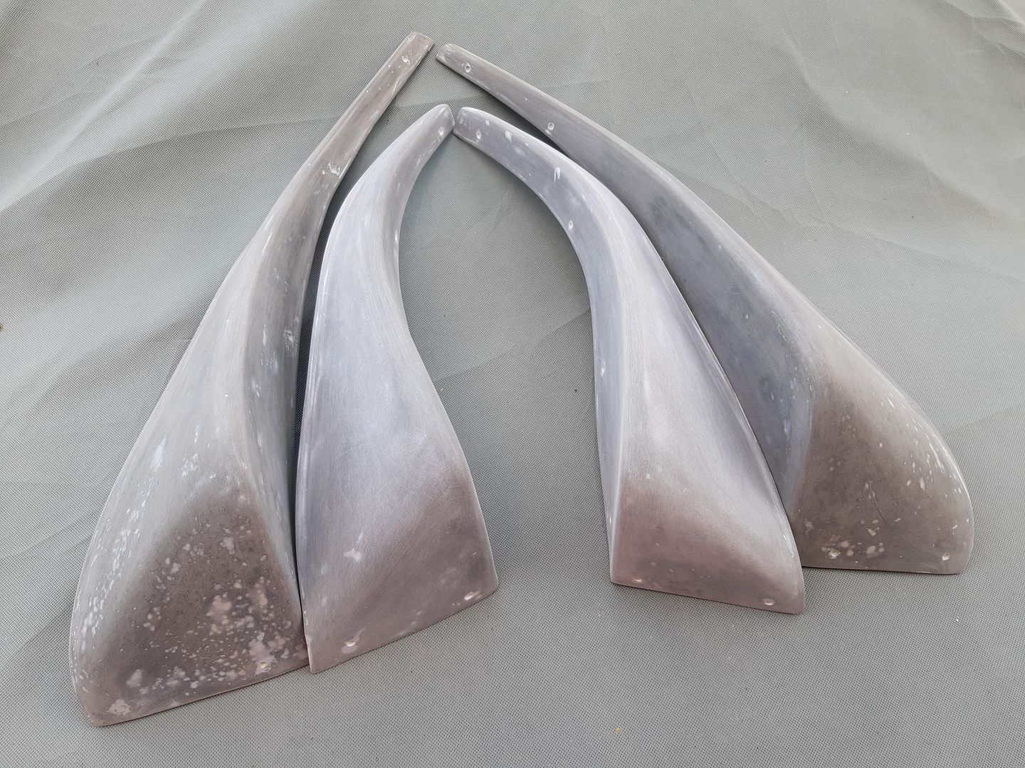
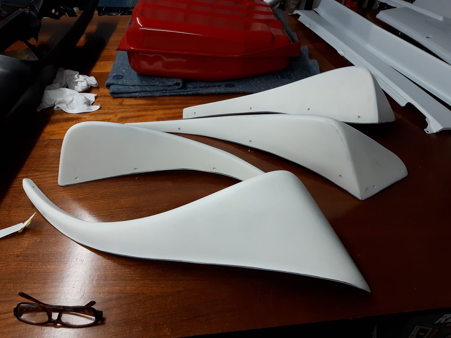
Some things we have to do twice and not by choice.  I'd completed the prep work on some flares that fit behind each wheel. Turned out that the modern high build primer expands/contracts at a different rate than the rubbery plastic the flares are made of. So over time while sitting around waiting for me to finish the car the primer cracked. I had to strip them all and start from scratch using epoxy primer this time which will hopefully cure the problem. I guess in a way it's better than if I'd quickly gotten the car in final paint only to have it crack afterward.

[URL=https://app.photobucket.com/u/NOTATA/a/ac949837-2452-4f6a-b3a7-1455f6a2f0b0/p/f0ef3d8e-c074-4990-baa8-ec74f5eb08c1][/URL]

[URL=https://app.photobucket.com/u/NOTATA/a/ac949837-2452-4f6a-b3a7-1455f6a2f0b0/p/2479603e-898f-4417-ae5f-923c4435c419][/URL]

Tony Sestito
Tony Sestito PowerDork
6/1/20 12:27 p.m.

Wow, sounds like you have been through the ringer. Wrenching can provide therapy for people like us. Hope you feel better, and keep fighting!

1 ... 8 9 10 11

You'll need to log in to post.

Our Preferred Partners
pqhJHlozSDStb3LYviU9xYz6aMsS22vl4jTGSGonrzbrSWM5Oti7bleJ0uGfLd03