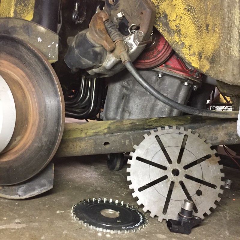
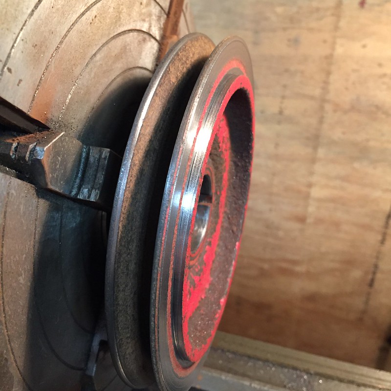
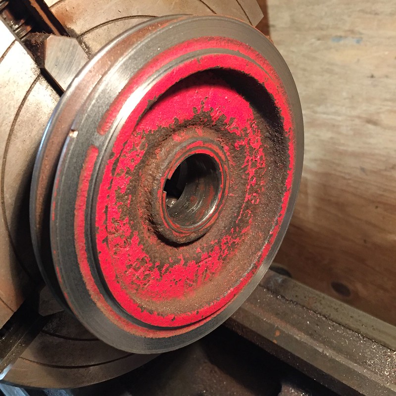
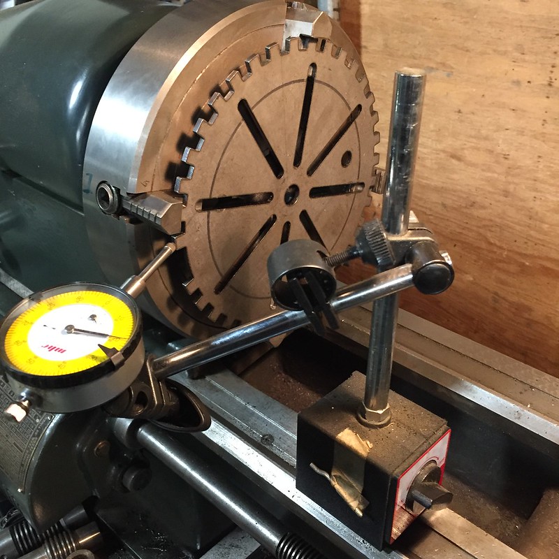
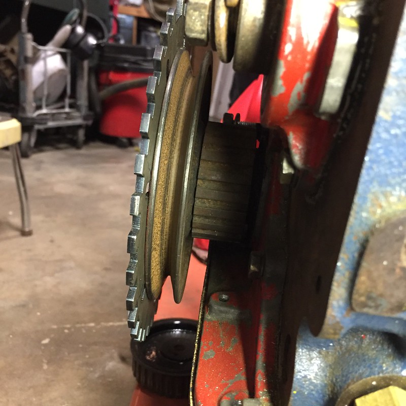
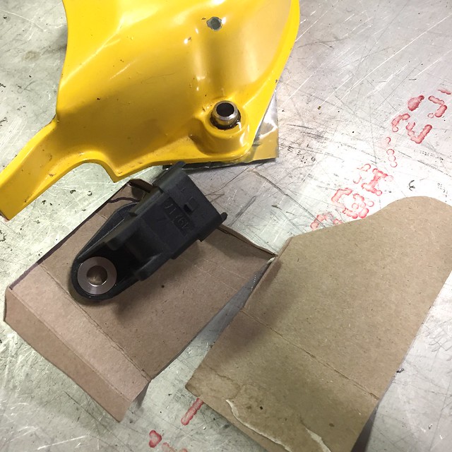
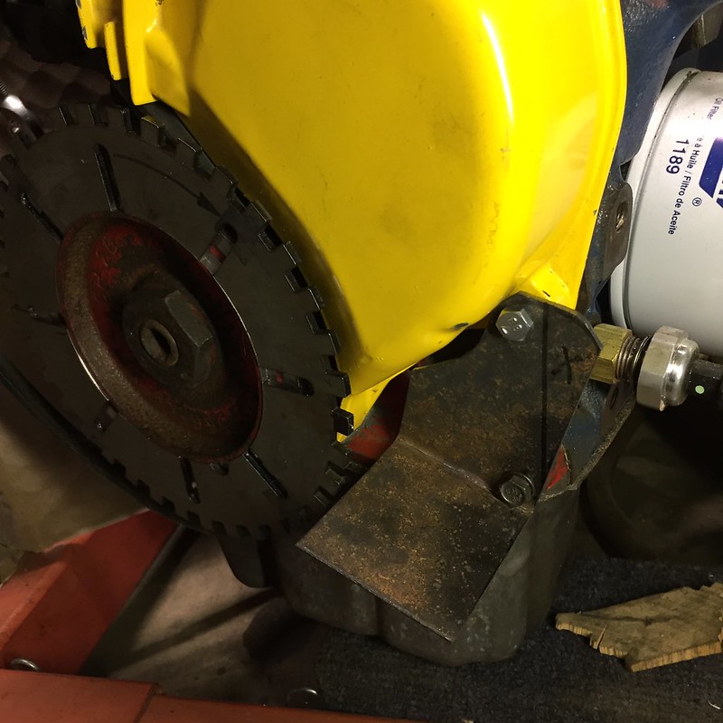
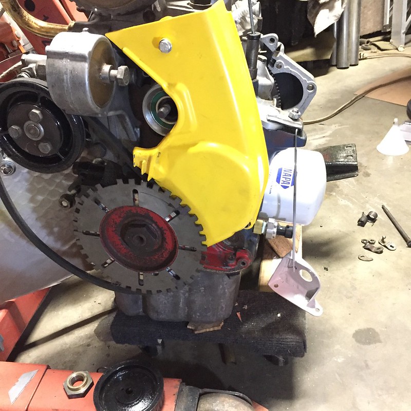
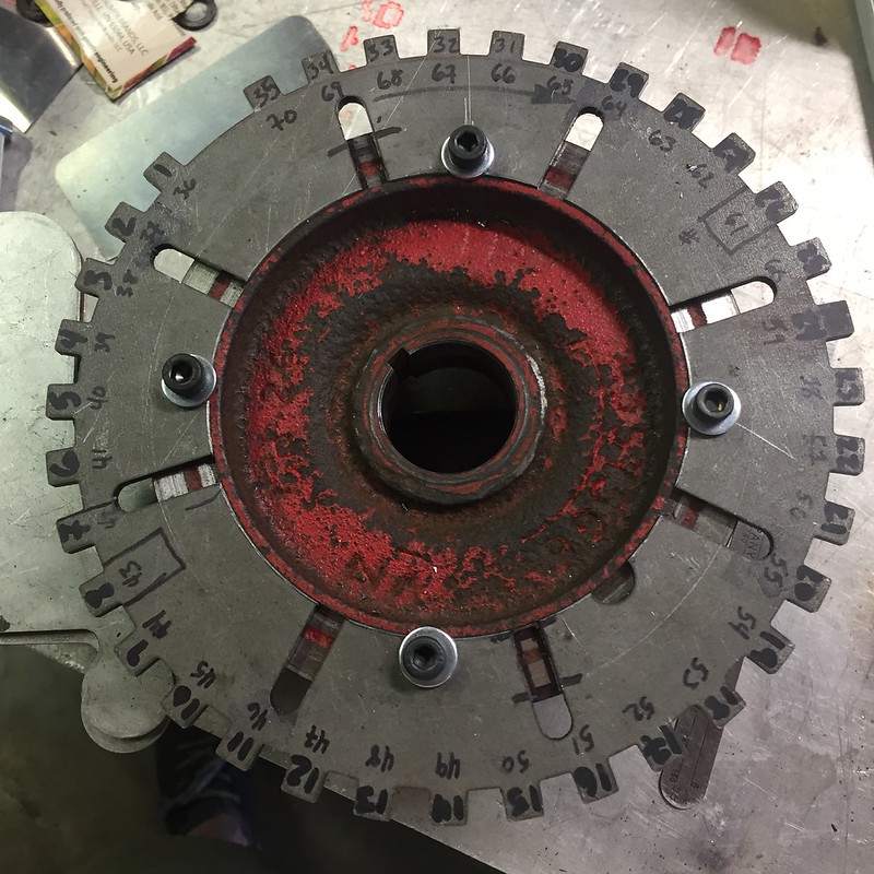
Lots of time invested noodling over the placement of my trigger wheel relative to TDC and the sensor. Like most 4 cylinders, this engine pairs cylinders 1 & 4 and 2 & 3 at TDC together, respectively. So all cylinders have TDC 180° from each other. I placed my missing tooth 90° from any TDC event, and set the sync tooth on the cam on the falling edge of tooth one (first tooth after the missing tooth).
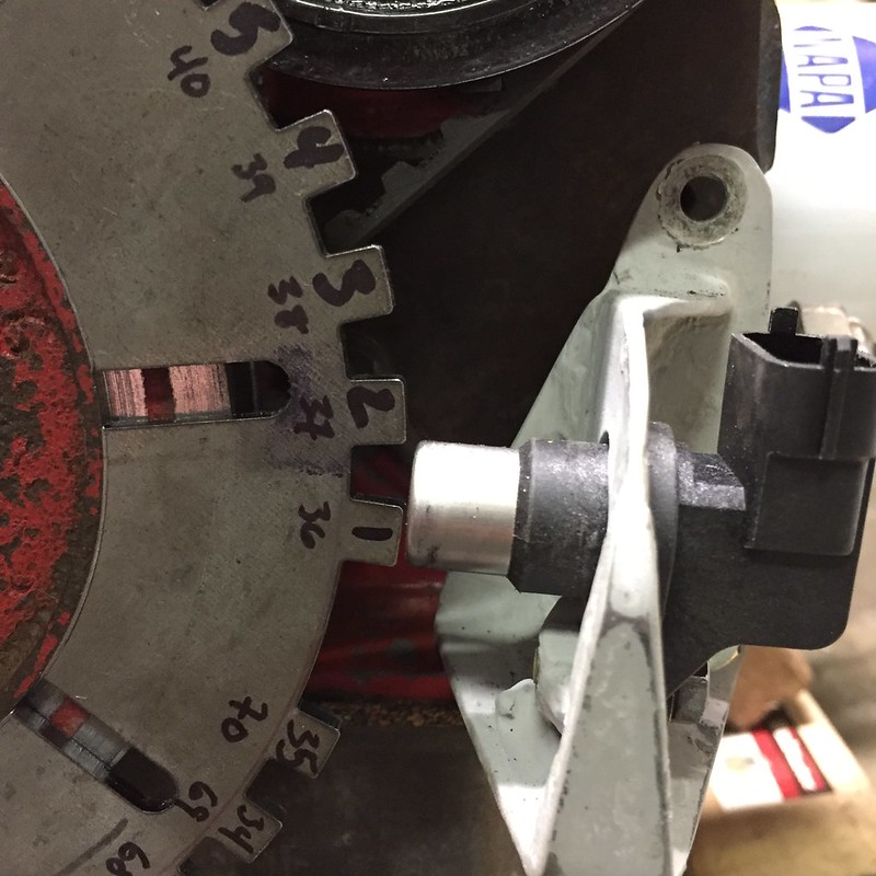
The firing order of the Lampredi is 1-3-4-2, but since my ECU will see cylinder 2 first after the missing tooth, my firing order gets changed to 2-1-3-4. Which is the same order, but it makes my head hurt a little not to have everything referenced from cylinder one. Remember the fun fact I mentioned back on page one or two about timing this engine? That's right: when the crank and cam are on their timing marks, you're ready to fire cylinder 4, not cylinder 1. Thanks Aurelio. None of this matters if you set the ECU up right. It just needs to know which tooth is TDC for which cylinder. Done with that task, I basically signed my death warrant and screwed the trigger wheel to the crank sheave. I'll slot the holes if I need to clock it a few degrees to get synced with the sync. The ECU has an oscilliscope built in, so that's one of the first things to test before actually adding fuel and spark and attempting to start the engine.
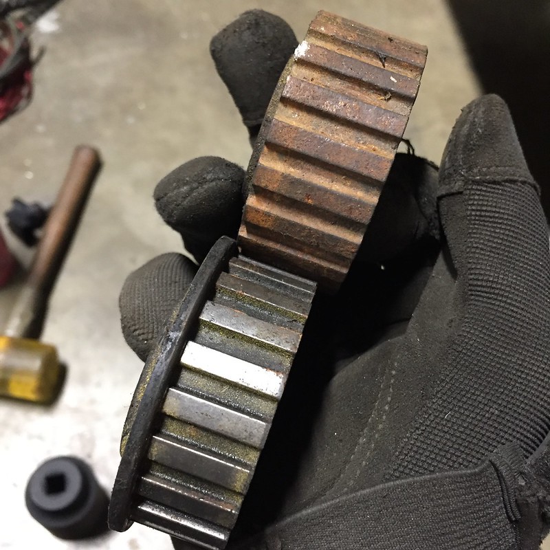
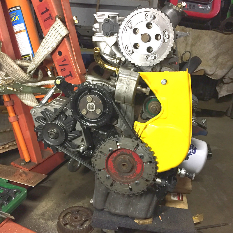
Getting everything timed and the sensors and triggers placed where they needed to be was SUPER tedious. I took the cam belt and cover and everything on and off at least a dozen times. It's aggravating that the timing belt cover is where the timing marks are, because you have to take it off to change the belt. You don't know if you accidentally moved something until after you perform the very last step. On the 1500 engine they changed this, but since I stayed 1300, I get to enjoy this feature. The order of operations is very specific too. Oh, you haven't put the v-belt on yet? That's ok, you can removed the CPS bracket and timing belt cover to put it on now.  I think it's buttoned up for now:
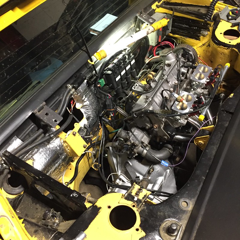
Did a little mock-up work on my throttle linkage. Think these zipties will hold? It only gives me about 60% throttle, so obviously a more permanent solution is planned. This might work for a first start though. Cable section is from a fuel injected 1500 throttle. I'm going to make a eccentric cam lobe on the idler arm (the part on the cam cover) to make it progressive.
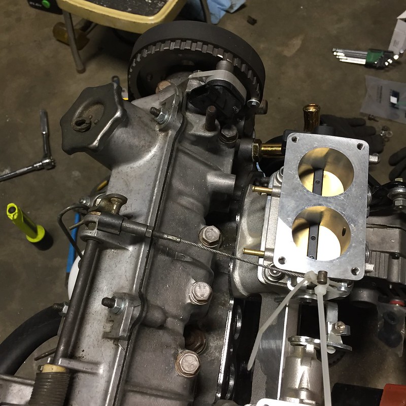
Honorable mention in the above photo - you can see the sync sensor tooth on the right side of the cam sprocket.
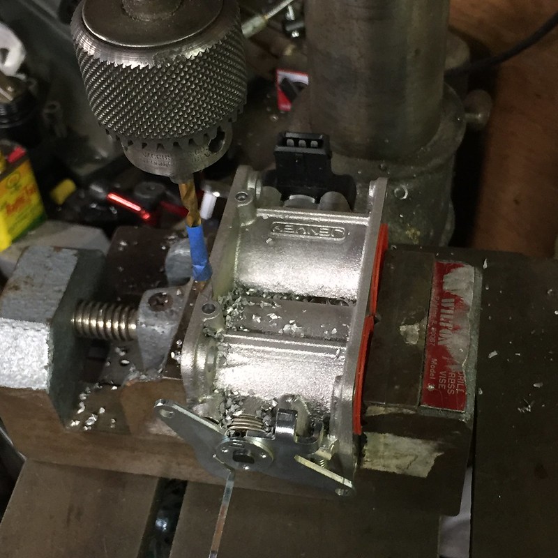
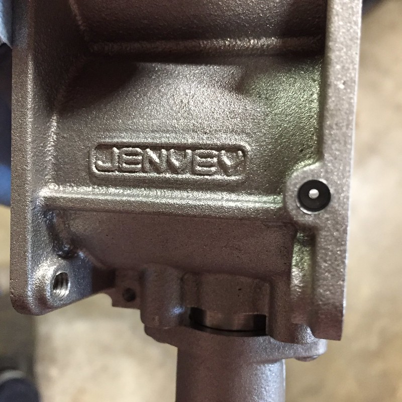
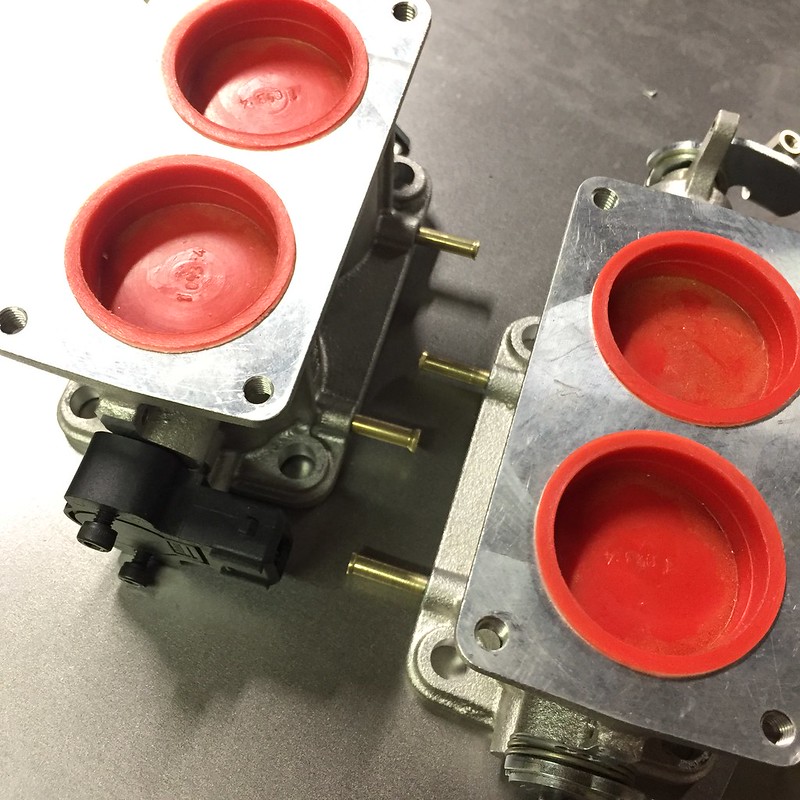
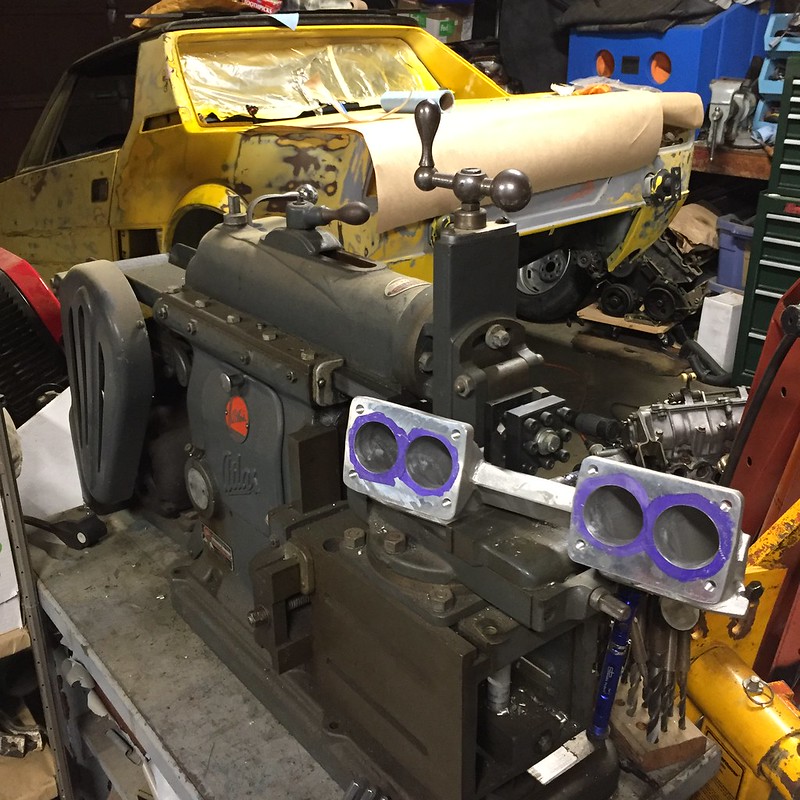
Speaking of throttles...finding the right o-ring for the Jenvey bodies has been giving me fits. This is the closest I've found so far:
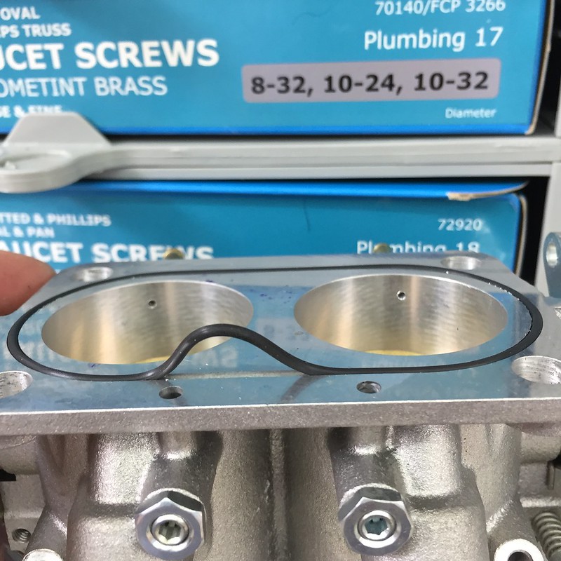
It's 1/16" thick, and about 3-3/16" diameter, or 81mm. I have two on order that might be close enough. If I fail there, I'll just cut some paper gasket material and be done.
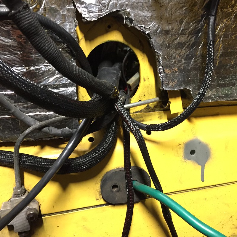
I finished up all my terminations. Fuel pump and reverse light switch are the only four terminations I have left to make, but I'll wait until everything is back in place before making those.
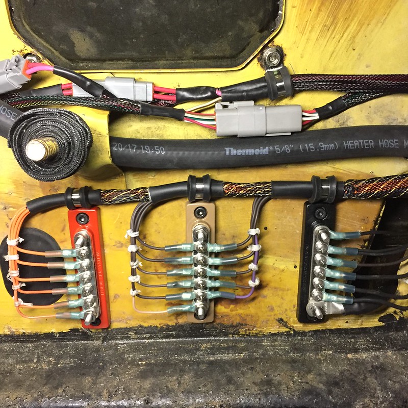
I wound up grounding the main ground bus on the right straight to the engine block instead of welding a ground stud to the body in the wiring bay. I'd been reading the Megamanual this weekend and remembered that specific piece of advice. No, I'm not using Megasquirt, but the Megamanual is so damn good, especially when you're mixing components from a gazillion different sources like I am. In the evenings this last week I got my base fuel and spark tables all filled in with some rough values that should be close enough to get the engine to run. I did math and VE calculations and stuff, which isn't particularly hard, but it does make you feel smart.
Final terminations made to my power distribution panel and main breaker. Fuel pressure regulator also visible here:
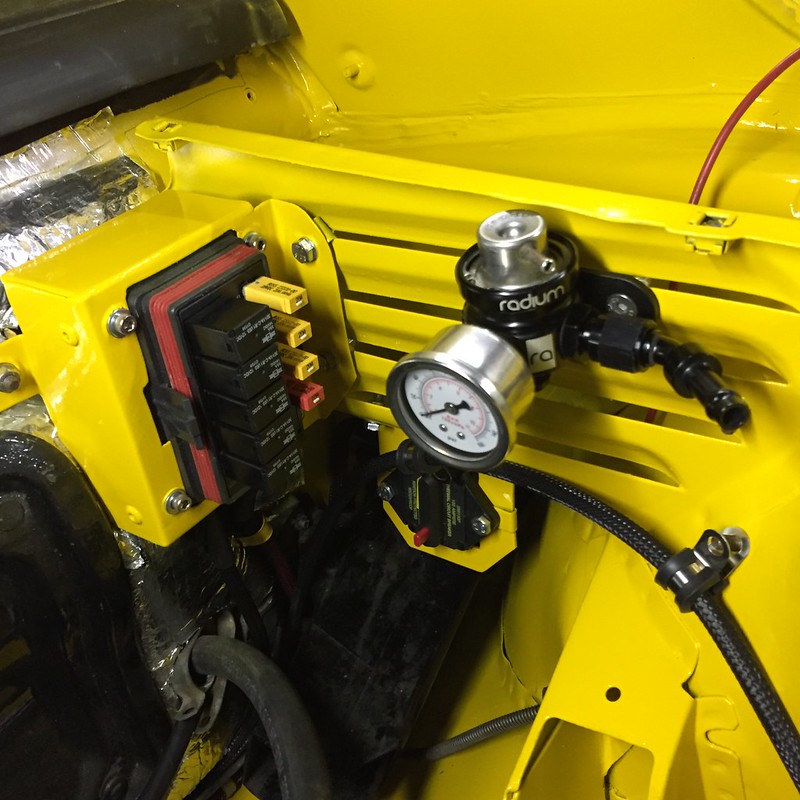
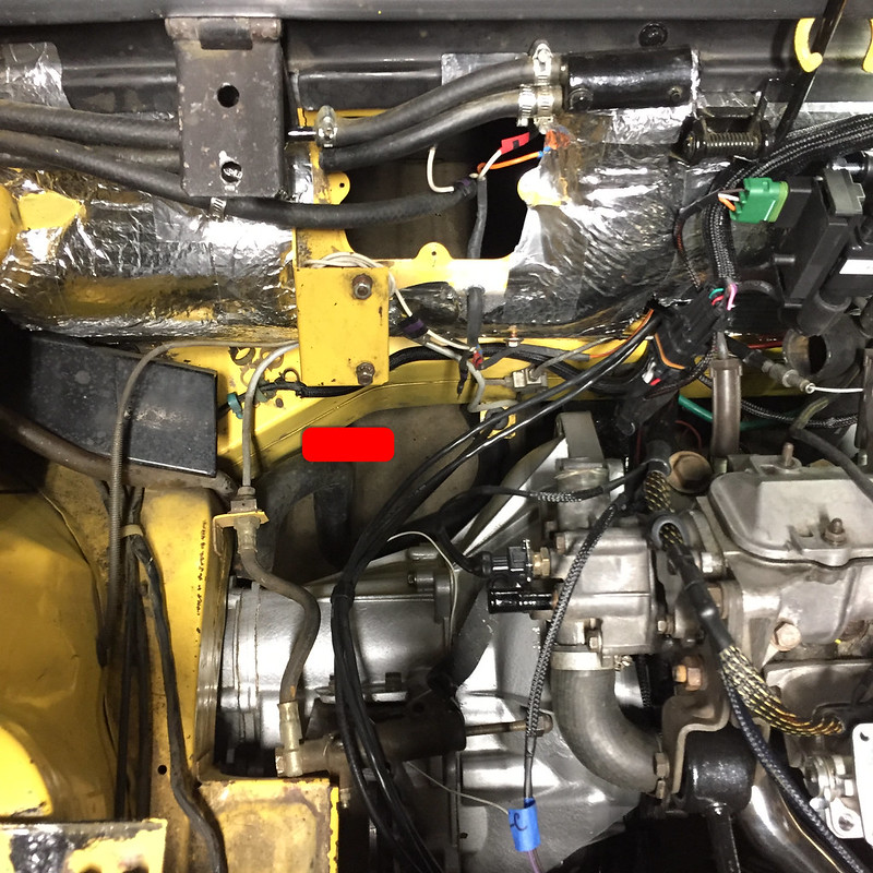
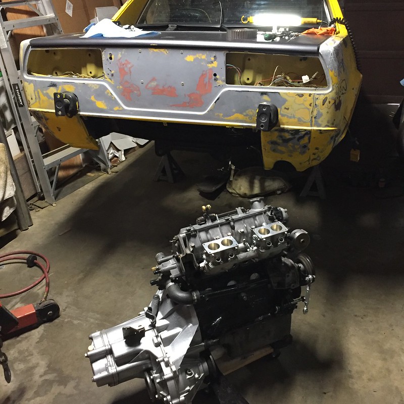
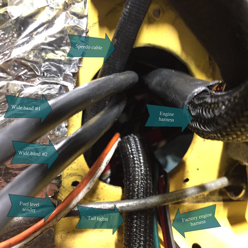
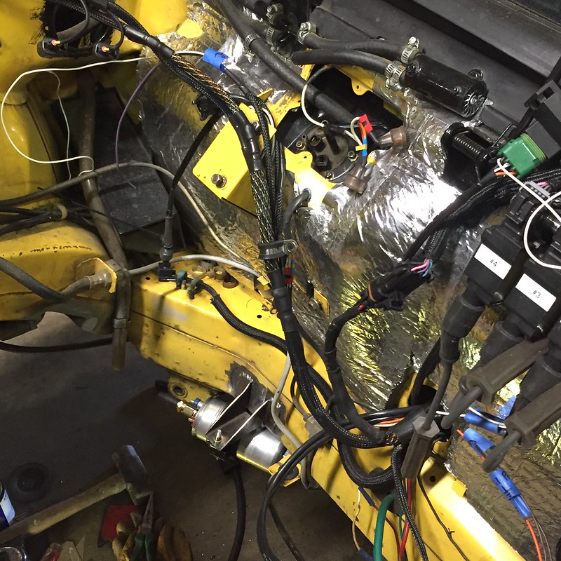
Ran all new wires to/from the alternator as well. There's a whole lot of braided loom happening in this engine bay now! I'm planning to slide the engine into the bay today or tomorrow as time allows.
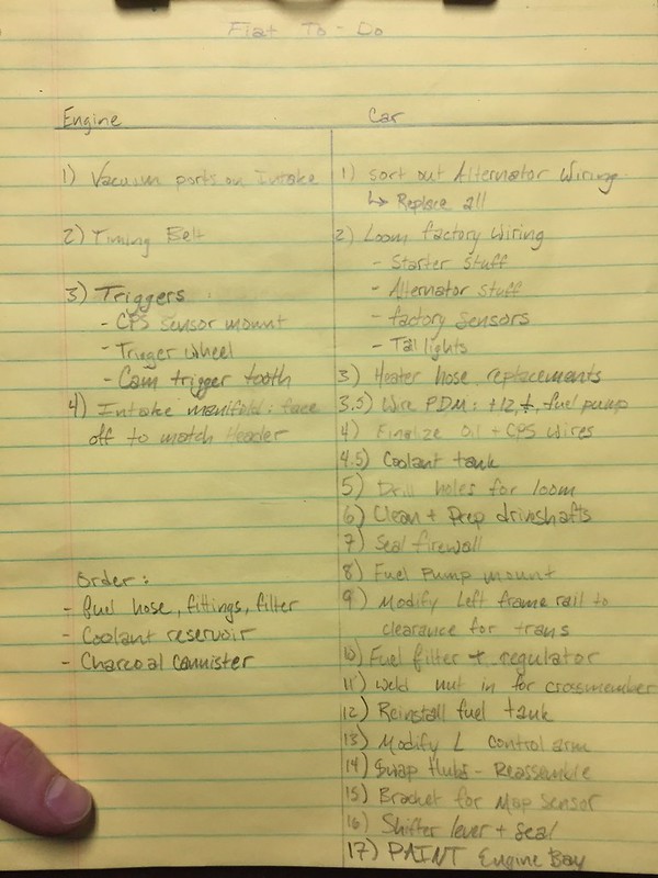
Ten days to complete the following tasks:
- bolt engine mounts up, connect wiring
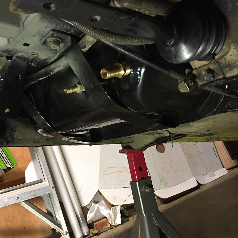
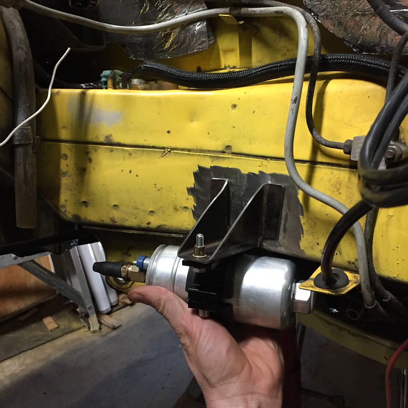
- Fit fuel system - it's basically all here, I just need to cut hoses to length and crimp the hose clamps on.
- Install battery
- Verify wiring works as expected from power distribution module: ECU, injectors, coils, and fuel pump have power
- Fill tank with fuel. Pressure test system.
- Connect ECU and laptop. Update firmware on ECU.
- Load base maps to ECU
- Crank engine with fuel and spark disabled to verify firing order, trigger signals, etc. Adjust as needed.
- Calibrate O2 sensor controler
- Calibrate TPS
- Enable fuel & spark, and attempt starting.
Bonus tasks:
- Modify driver's side control arm to clear transaxle housing
- Swap in new 5-speed hub uprights
- Clean and install new CVs. Build out drive shafts.
- Reinstall suspension
- Replace driver's rear caliper and install braided brake lines all four corners
- Fabricate mount for coolant reservoir. Install
