
I've been a lurker for a while on Grassroots and enjoy the home built nature and back yard ingenuity. I've been looking for a place to get some build exposure across a broader car interest range and I think this is just the place. I do everything I can in my builds from design, to machining, welding, painting, engine building and tuning, etc. About all I can't do is the engine machining due to access to the specialized machines. Though I put allot of thought into each step of my build I'm open to all ideas and look forward to the feedback and thoughts from everyone.
The back story: This car began as a 3.0l shadow that I changed to be 2.4 turbo running a best of 10.79@135.9. Late in the 2012 season I performed a spectacular 1-2-1 shift going down the track which left the car dead on the sidelines. Getting home I couldn't find any mechanical damage except for all the flywheel bolts had come loose. I also lost the crank signal but since I had plans to upgrade the turbo and header I just pulled the engine instead of troubleshooting it at the time. A new acreage, a second kid and a whole bunch of life later and I am finally able to start on things again. What I did find is that when you have 4 years to think about things a simple turbo change has the capability to really explode. The worst part of that time is going to SDAC (Shelby Dodge Auto Club national convention) and taking about possibilities which really make your imagination sore. As a result of discussions at SDAC 25 I made the choice to go RWD and really try to challenge my design and fabrication skills.
For a build log of part 1 you can visit the following link: 93 Shadow Part 1
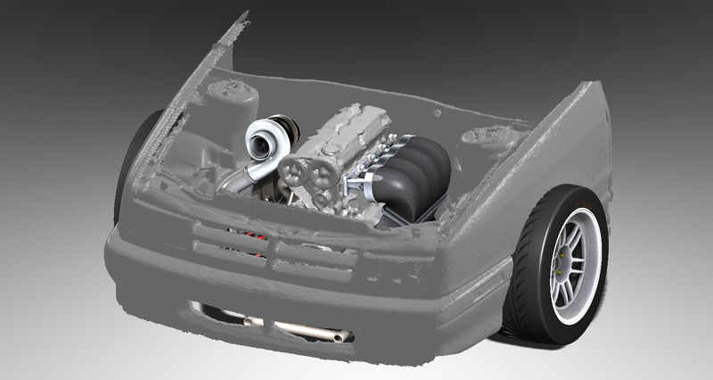
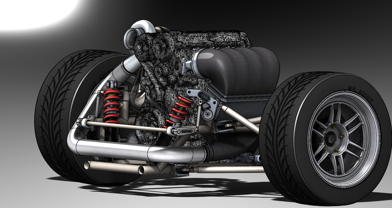
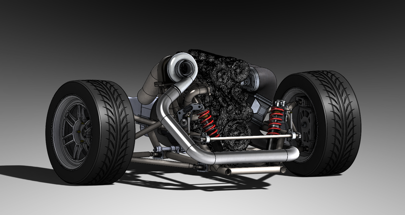
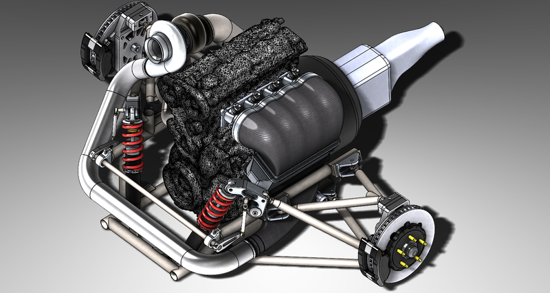
In July of 2015 I began the design process and modelling which gets me to where I'm at now. Many, many.......many iterations later I have what I feel is very close to a final design. As you can see there are still missing components but I thought I would start the thread now to allow others to follow in some final stages of the design and FEA as I check off components as complete and ready for fabrication. This will not be as fast as my other build, which still took 2 years, but I hope to come out with something I'm really proud of. My current goal is in the 4-5 year mark so hopefully I can keep everyone interested that long.
For now here are some screen shots. I'll come back and post my current design specs and hopefully be able to answer any questions that may arise. I'm looking forward to the whole process and I hope my mom will be proud.
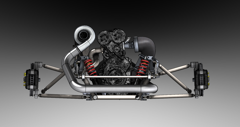
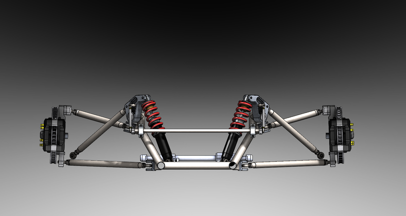
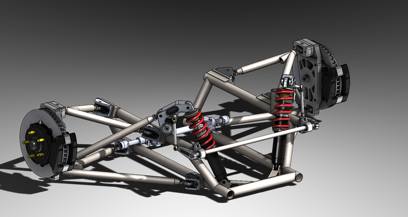
Wow, 49 pages for the initial build  . I skimmed the first page, but want to go back and look at it all in much more detail. Looks really cool!
In reply to NoPermitNeeded:
It will have a water to air which is located between the lower intake and upper plenum of the ITB intake. I have some more updates I'll roll out, one of which shows this better. :)
I saw this car run back at the SDAC that was held in Hagerstown, MD about 7 years ago.
In reply to Sky_Render:
Nice! Hagerstown was a haul for me. Definitely the furthest I have ever drove it being 2270 miles one way. Tiring but a great time as it always is.
turboshad wrote:
In reply to Sky_Render:
Nice! Hagerstown was a haul for me. Definitely the furthest I have ever drove it being 2270 miles one way. Tiring but a great time as it always is.
I had that black Plymouth Sundance Duster with the gold wheels and decals.
I miss that little car. 
So this is the same 2.4 that was used in the cloud cars, caliber, PT cruiser, and turbocharged in the PT Cruiser GT and SRT-4? I've had an eye out for this motor for a little while for a project, but I've struggled with figuring out what FWD transaxles fit, and what an assembled weight for the motor is.
This looks like a great project - I'll be checking out your original build soon.

Mezzanine wrote:
So this is the same 2.4 that was used in the cloud cars, caliber, PT cruiser, and turbocharged in the PT Cruiser GT and SRT-4? I've had an eye out for this motor for a little while for a project, but I've struggled with figuring out what FWD transaxles fit, and what an assembled weight for the motor is.
This looks like a great project - I'll be checking out your original build soon.
Yep. Its a larger version of the 2.0 used in the Neon and shares most of the bellhousing and cylinder head mounting points with the earlier 2.2/2.5L Chrysler motors. Although there are differences in the blocks, so accessories and other errata are different.
Basically the Neon/Stratus/PT all were available with a manual box. The SRT4 had the strongest and most years had a factory limited slip installed. In your case, I would grab a donor from a PT Cuiser GT (Turbo) if you can't find a SRT4 donor. There's a board member in Vancouver building a MidLana using a SRT4 drivetrain, check out his build thread there was discussion of the 2.4 variants, etc.
In reply to Stefan:
Oh yeah! I'd forgotten all about bgkast's thread! I'd be interested in building up a N/A 2.4...word on some super sketchy dodge forums is that with basic head/cam work 200hp isn't difficult. I haven't seen any dyno results though. 
I'd believe that. Dodge got 300hp from the 2.0L using the stock ignition system and a lot of compression and port work when used in the NATCC. Gave the Honda's complete fits on the longer tracks :)
I suspect that using the stock cams with decent valve and port work combined with more compression you'd get a pretty drivable aka faster 200hp engine. The intake manifolds seem to make quite a difference, so pay attention to that as there were many variations available.

DrBoost
UltimaDork
2/2/17 5:02 p.m.
Mopar used to (still does???) offer a RWD conversion for the 318/360 for these cars. Can you use any of these parts as a short cut?
Whoa DJ found his way to GRM.
In reply to Mezzanine:
Yes, pretty much like Stefan said. My in particular is from a 95 Stratus and in 2000 they changed the port design and crank trigger. The turbo blocks would then obviously have an oil drain too. I agree that the easiest route would be starting with a PT GT or SRT4 engine to drop in.
In reply to DrBoost:
All the RWD kits I've seen are for V8s with a SRA. I'll be retaining the 4 cyl and using a Ford IRS. Also I've done away with the whole front end so none of their mounts would do me much good.
In reply to miniva_racer:
Hahaha, I guess I have, I can't let you guys have all the fun. 

During my learning and research I found it very easy to come across definitions and calculations for all aspects of the suspension geometry. Finding actual starting points, on the other hand, was very challenging. I know every project is different but it was quite difficult to even find a good place to start. So here is what I've designed the suspension to and will begin with. I'll throw in some explanations of why I came up with the number where I can to a: maybe help someone else out who is reading this and b: to help me remember why I did it. ;) I have no idea right now if these numbers are going to work well but it is my best educated guess of where to start and I can let you know how it actually works in a few years. If anyone with more experience then I sees any grave errors please chime in with an explanation. Thanks. :D
Front suspension specs:
Ride Height - 4.5" because a speed bump is 4" though I will still be doing my best to avoid all of them.
Travel - 2.5" in bounce and rebound. No real scientific reason, it just seemed like a good place to start when reading about other people’s builds.
Static Roll center - Right now it is sitting approximately 3.06" above the ground. My goal was to have 1" of RC movement per 1" of body travel and I didn't want it to transition past the ground plane. The 1:1 goal came from the attempt to maintain similar jacking forces throughout the whole suspension travel to keep the handling predictable. I was able to achieve an average of 1.04"/1" of bounce and 1.12"/1" of rebound. This may change slightly by the end but for the most part should stay in this range.
Scrub Radius – Scrub was a hard one. The information is so vague that I almost had to take the first bit of solid numbers I could find. There are a million sites explaining what it is and a half million saying some is good but not too much but no one says how much is some. I finally found a source stating Carroll smith uses 10% of the wheel width and a guy name Joe Cheng says 5%. Well to keep the KPI from getting bigger than I wanted I settled on 1.24” with a 10” wide wheel.
King Pin/Steering Angle Inclination (KPI or SAI) – This is a big compromise as it has to do mostly with packaging while trying to get the scrub radius you want. The unfortunate part is KPI will add camber as the wheel turns in both directions. Great when it is the inside wheel but not so good when it’s the outside. Therefore you don’t want to large of a KPI so I settled on 10° to get the scrub radius down to 1.24”. 12° would have put me just under 1” of scrub radius but I chose to sacrifice some scrub for less KPI. Good choice? I have no idea.
Caster Angle – Caster will combat KPI as it will subtract camber from the outside wheel and add to the inside wheel. The scrub radius and mechanical trail set by the caster contribute to the self centering of the wheels. Too much caster resulting in too much mechanical trail can result in a car that is hard to turn. This is one reason you also don’t want to much KPI. It seems that a caster angle of about half your KPI is a good place to start so I currently have a zero point of 6° with +/- 2° of adjustment. Hopefully that will be enough.
Camber – I’m going to start with -1.5° of static camber with an adjustability of +1.5°/-2.0°. I think this will be fine to play around with.
I still need to run through some more dynamic geometry tests but I don’t see these numbers changing all that much. Once again I am really just making my best educated guess. The true test will be once the car is together and drivable. I may fluke it off or find myself making new parts to get the car handling how I want.
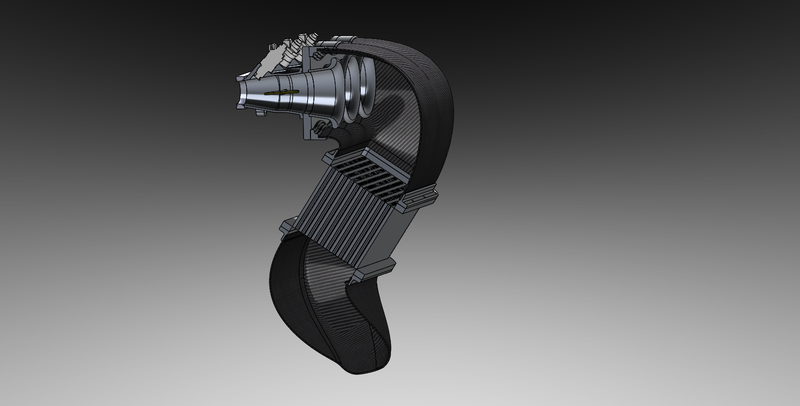
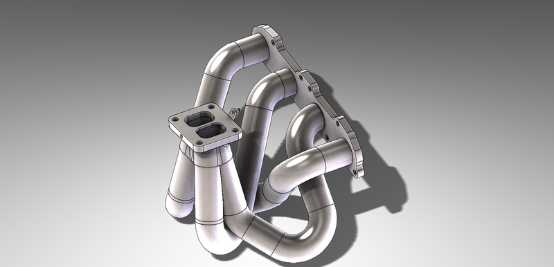
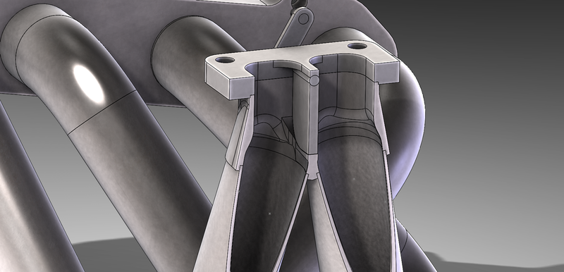
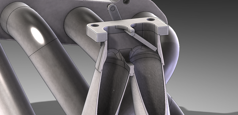
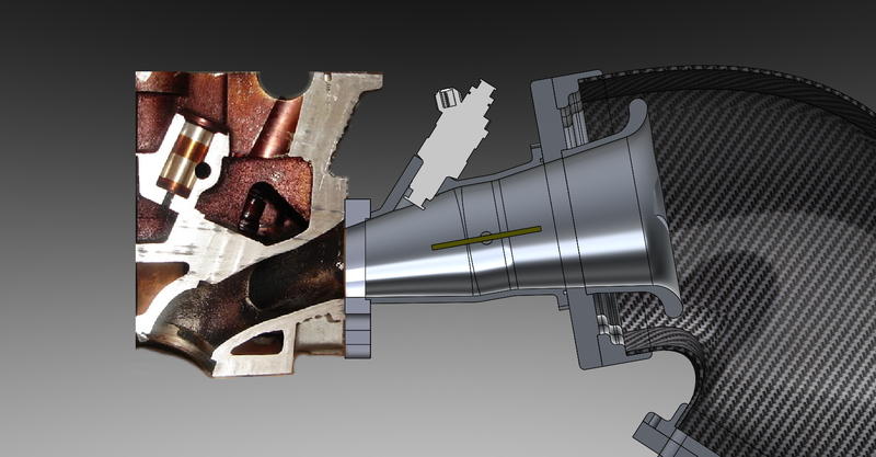
Also, here are a couple shots of the intake and header. The intake (if I can pull it off) will have a carbon inlet to a water to air IC that goes into a carbon plenum to tapered ITBs. I think this will be one of or the most challenging part of the build. I’m excited to try it and here’s to hoping I don’t spend too much money failing. :D The header will be 1 7/8” thin wall SS with my own version of a quick spool valve. I don’t like any of the ones I’ve seen since they don’t utilize the advantages of a twin scroll exhaust keeping the pulses separated. I am going to make my valve in the collector so the division is maintained under high boost. It also will not have any additional hardware in the flow of one of the scrolls like the butterfly valve types do. The plan is to control it with a servo motor so I can write a spool curve in the ecu and tune it for smooth operation.
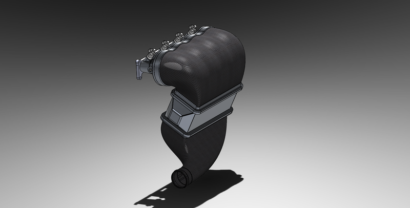
Your ability to plan and sort through problems virtually is to be commended.
I haven't followed SDAC stuff since maybe SDAC6? They were always a great group of guys.
In reply to mazdeuce:
Thanks, but I think I'm waiting to see if I can actually build my virtual plan. 
I've started doing some FEA and so far things are looking good with only minor modifications. I'll be sure to post that up when I'm done with some explanation for those who find it interesting.
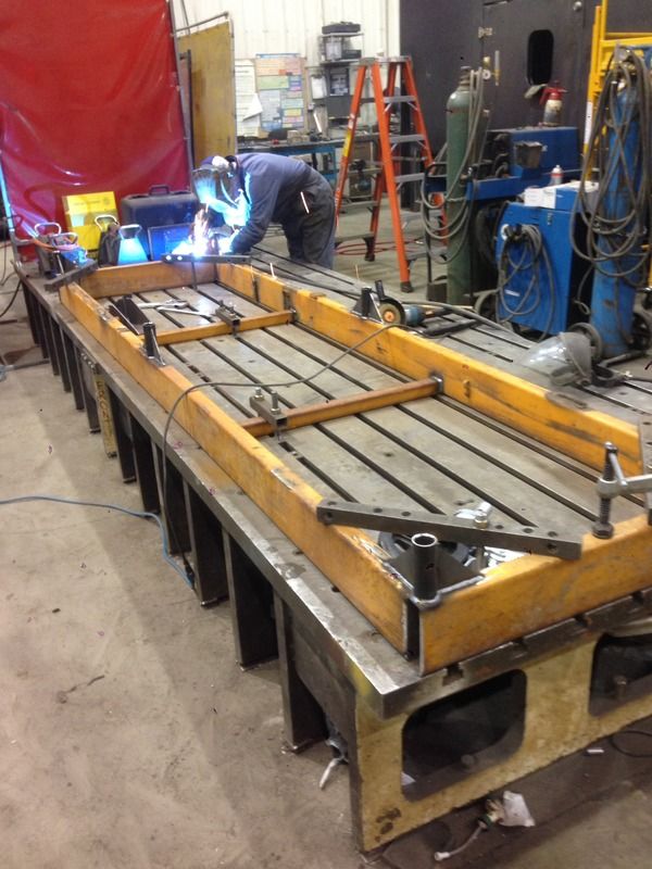
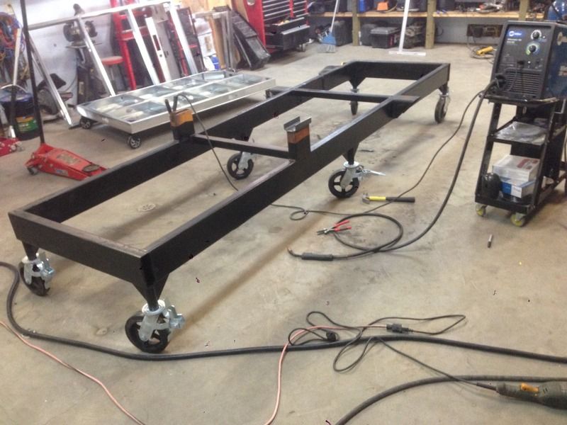
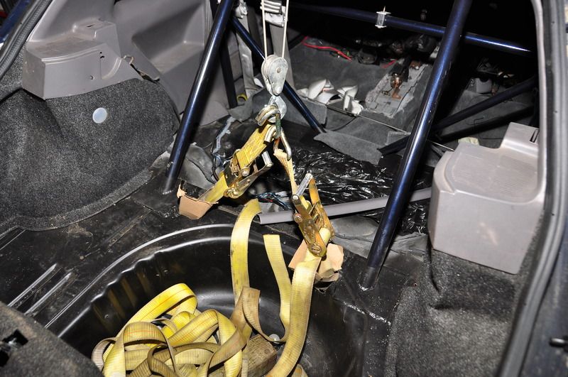
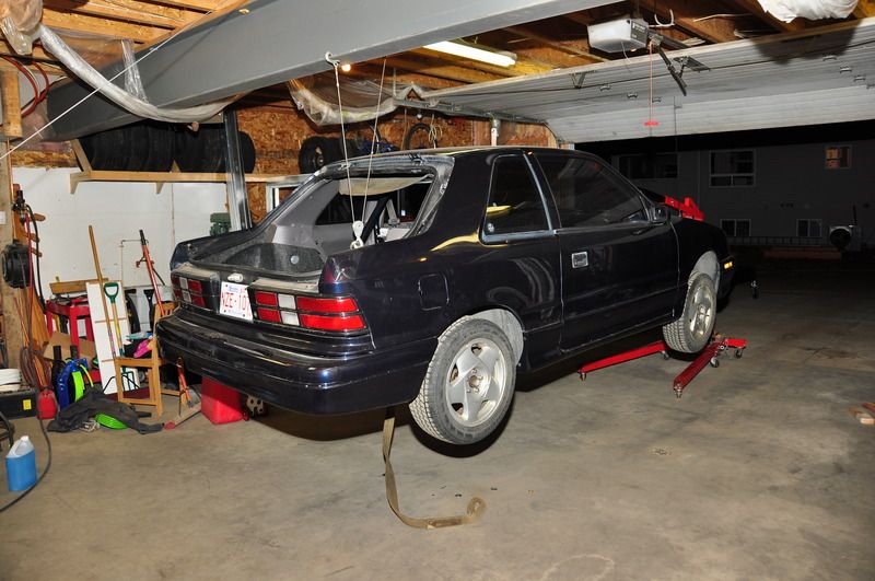
In the meantime I was able to get some free metal from work and build an assembly table. Big thanks to Don, one of our welders, for helping get everything perfectly straight and square as this is what I will be basing most of my measurements off of. Getting the car onto the rack was quite an adventure. Since I don't have a car hoist or a jack that can go that high I had to get my MacGyver on with a touch of Missouri red neck. It looks worse that what it was but it was "fairly" stable while performing the feat though I didn't dare go underneath it and only got as close as I had to. With a wall winch over a beam in my garage in the back and the engine hoist up front I was able to get the car far enough off the ground to mount to the rack. I think the pictures will speak for themselves. ;)
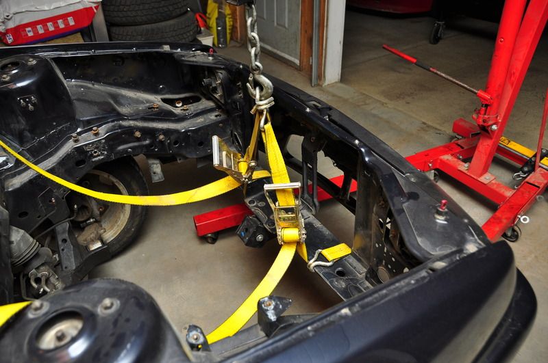
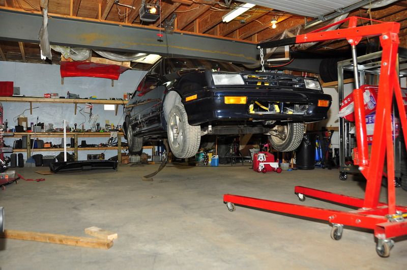

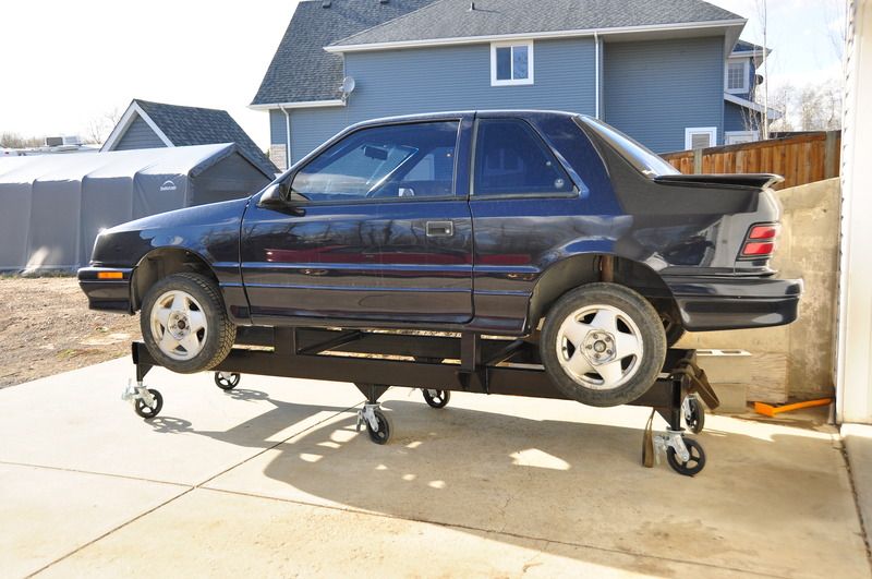

I did some work with the intake today. Tilted the runners 10° to match the ports better and I thought this made for a cool pic.
I've gotten through some FEA and so far things are looking good. I am close to finalizing the front end design which means I can then start building and more importantly machining. Here are some nice colorful pictures of full straight line braking for you to enjoy in pure nerd form.
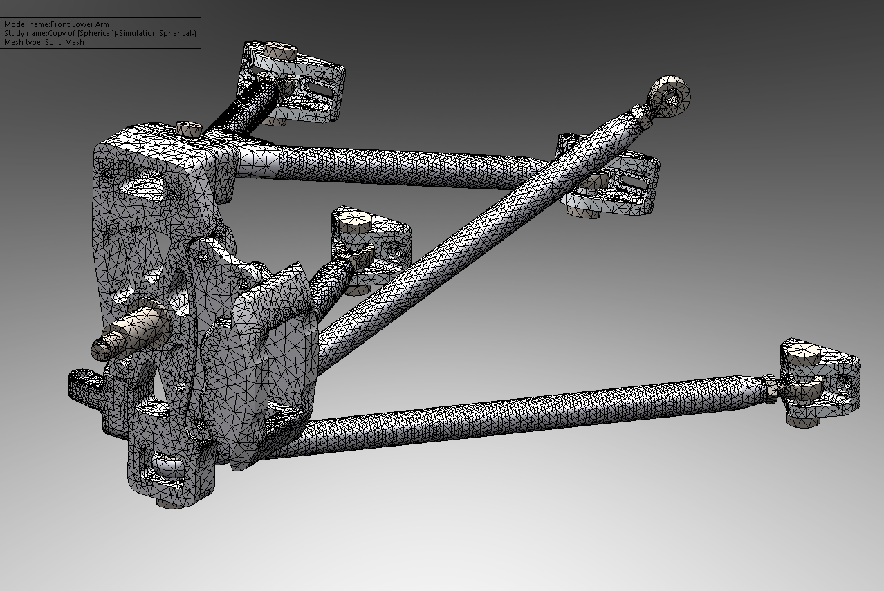
First is a mesh plot. This is a necessary step in FEA so the computer knows how to segment to part to make its calculations. Each node formed by the triangles will get calculated and assigned a stress and displacement by the solver. This will then allow the generation of rainbows and boring videos to see how your parts will react under load.
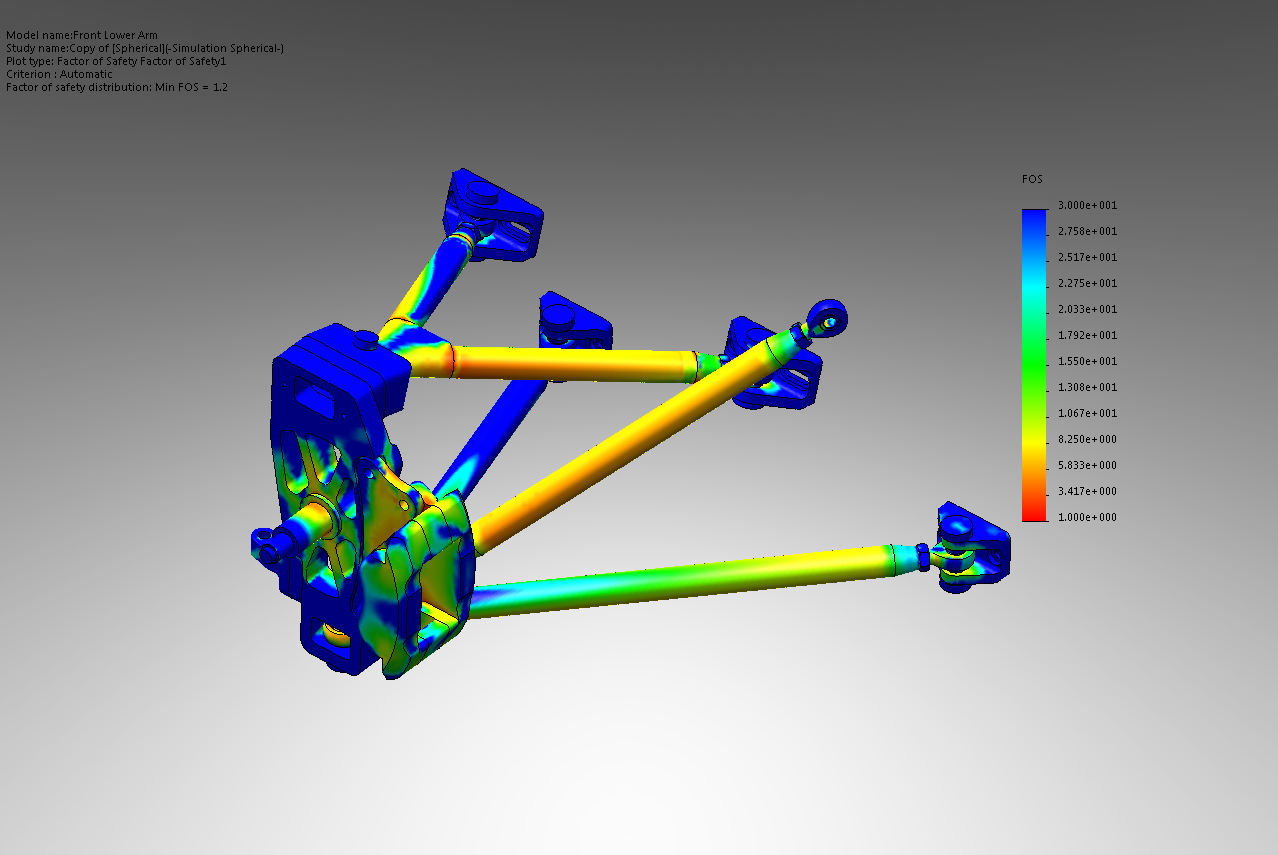
Once meshed the FEA solver can do its job and calculate all the values depending on how the part is constrained and loaded. This plot shows the results in terms of the factor of safety. The factory of safety in this case is a ratio of total stress to the yield stress of the material. Simply put anything above a FOS of 1 won't yield and anything below will. This type of plot is quite useful when multiple material types are used such as aluminum and steel in this case. It lets me see how close the whole system is to its given yield strengths. With a straight stress plot I would have to determine and calculate the highest stress areas to see if it is OK in the material it is present in. Another useful feature, though very boring in pictures, is the ability to hide all areas below or above certain FOS values. This lets me see where the stress is starting and watch it "grow" through the part giving distinct stress paths. In this particular plot the scale is from 1 (red) to 30 (blue) to show the FOS distribution through the parts. The test was done with 1250lbf of vertical load and 1250lbf of horizontal load with 1450ftlb of torque from the brake caliper in a clockwise rotation.
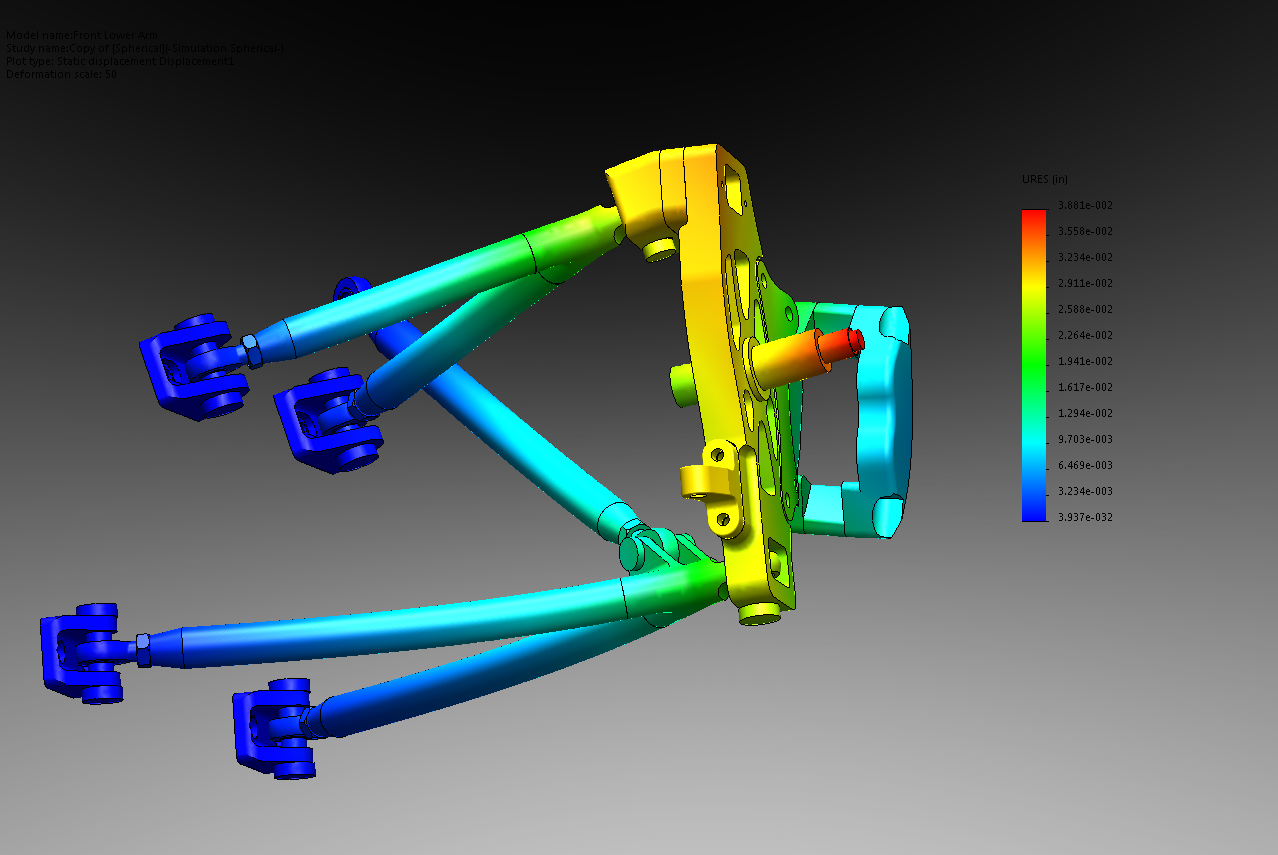
This last plot shows the displacement magnified 50 times more visually than real life. The scale shows a maximum total system deflection of 0.039" which is shown in red and gets less as the colors fade to blue. I like these plots to see how the pieces will deform as well as I can see if the deformation is realistic to what I expect to know if I have constrained and loaded the model properly.
Here is a link to what I've been told is a boring video of the displacement happening. It is better to see on a loop cycling in both directions but this is all I got converting out to an avi. and I'm too lazy to edit.
FEA Displacement
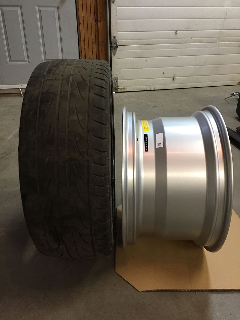
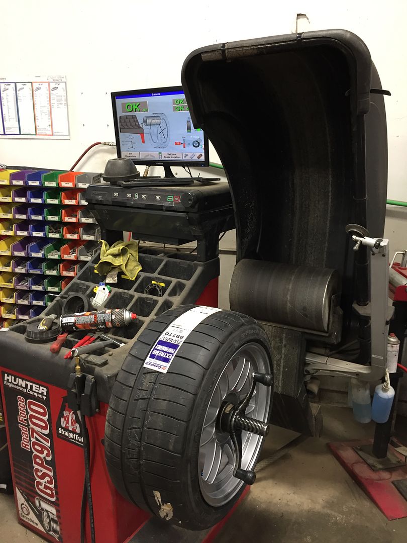
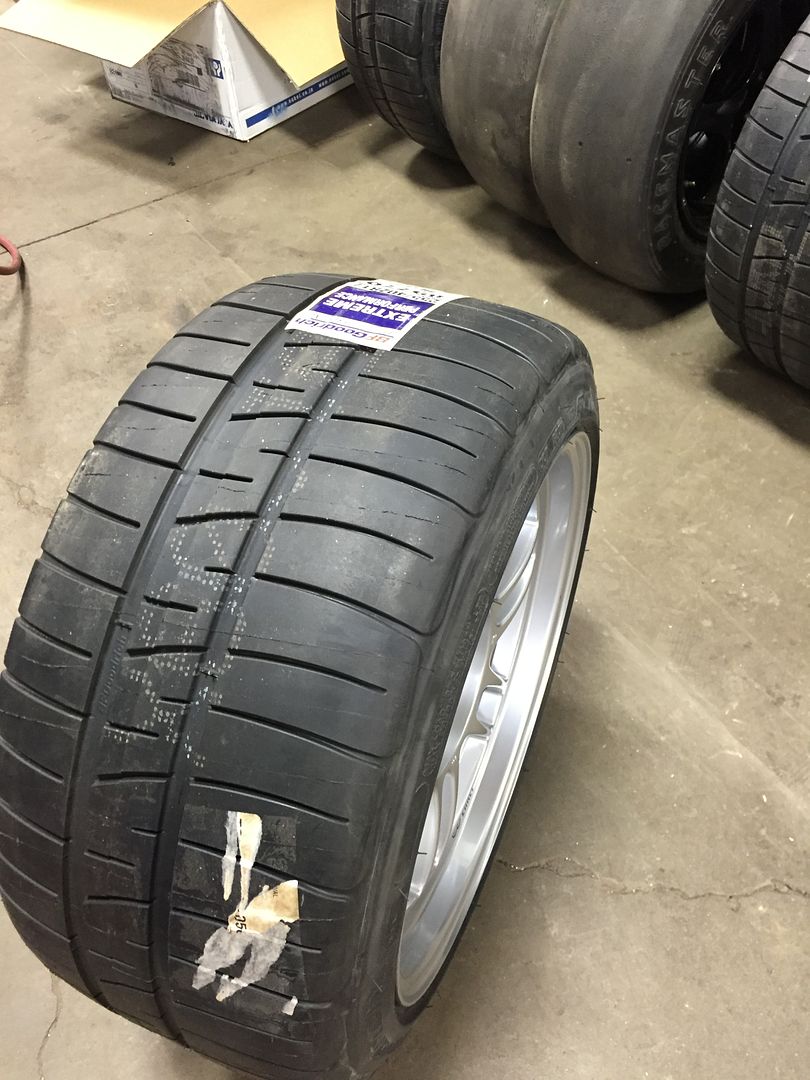
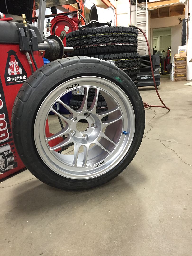
I don't know if the above is interesting to others but I thought I'd try to explain some of the process to those not familiar with it. Feel free to ask any questions and I will do my best to answer them. On a more material note, and probably more interesting to most, I received my wheels and tires and got them mounted. They are 255/40r17 BF Goodrich Rivals on Enkei RPF1 17x10 wheels with an 18mm offset. They have a bit of stretch using a 10" wheel with a 10" tire but this should help get the most traction out of them I can. The first compares the 17x10 Enkei wheel to my previous 215/45r17s, the rest are just to make it look like I'm actually accomplishing something. ;)
First of all- cool project! I've always thought the 2.4 turbo would be a hoot in something RWD, just never thought that it would still be a formerly FWD Mopar!
Now some annoying armchair quarterbacking (armchair engineering?): FOS of 1.2 is terrifyingly low, but of course it depends on what your load case is. It seems like you're trying to simulate hard braking [edit, went back and read it again, yep!] I would think you'd want the tie rod to be part of the simulation, I'm guessing you have that attachment point set to "fixed"? I'd also recommend trying the hard braking load case with cornering included, the side load and wheel being turned can do funny things to the forces the upright sees- especially if you hit a bigass bump at the same time. You probably already know all of this and much more, but former FSAE nerds like me will always wonder what all of the parameters for the FEA are unless we're actually sitting in front of the computer it's running on 
You planning on using all Heim joints?

In reply to ¯_(ツ)_/¯:
I agree with everything you've said and I appreciate the feedback and questions. I was also part of our FSAE team so I know the thoughts you get when looking at other designs.  For the first little bit much of this log is being transferred from another site so it is in a sense a little outdated. That being said with this many details there is always something that can get missed and hopefully you might have an opinion on something I've been struggling with.
I generally shoot for a min FOS of 3 while trying to filter out anomalies and consider the probability and frequency of loading. You are correct that the particular model is hard inline braking. The tie rod attachment point is fixed horizontally with allowed rotation and vertical translation. While analyzing these results I realized that I really needed to add the brake disc as it adds rigidity to the caliper when clamped. This definitely helped things out and I also switched the upright to 7075 vs the 6061 in this case. With some more design tweaks I was able to get the FOS to acceptable levels while also taking into consideration the fatigue limit of the material.
Now what I have been sort of struggling with is what kind of realistic steering angle and braking combination would I expect to see the worst loads at? Full lock no braking right before traction loss such as a skid pad? Full braking into a turn with partial steering angle while balancing the forces within the traction circle? Any thoughts? I haven't completed this part yet but I also haven't considered the design final enough to machine yet either. 
In reply to Sky_Render:
Yes, they are all QA1 XM Chromoly rod ends on the inside and YPB-T spherical bearings on the outside.

Assuming you're not limited on FEA time, once you think you have things mostly right I would run every nightmare scenario you can think of: full lock, hard braking, into a pothole, tie rod included that sort of thing. Of course it wouldn't hurt to try other steering angles, but usually being at the extreme ends of where things can move is what gets you the worst case. Also consider that, if you spin, you could actually be trying to threshold brake while going backwards, with a lot of force yanking the tire outwards working all of your steering geometry against you (negative trail!  ) and slamming the rack into its' stops.
Generally speaking, steady state is rarely the issue- what's going to break your E36 M3 is shock loading. Slamming into potholes, catching air, the backwards steering slam above... I would need to do some math to figure out the loading for these things, but I wouldn't expect something with a FOS of 3 in an ideal steady state scenario to survive all of it.
Our rule of thumb with the formula cars was, if the gusset/thicker tube/heavier machined part doubled the FOS and weighed less than the poo the driver would take before belting in, we'd add it- and the car built with that in mind was only ~20lbs heavier than the one where we saved every ounce and the damn thing never broke.


