The throttle servo was a cast iron bi*ch to sort out. The trouble was due to three different technological hurdles to jump. Physical hardware, electrical hardware and virtual software. .... plus add safety, speed and durability.
The first-generation of the throttle servo started by harvesting a stepper motor and gearbox from a laser printer. A wooden baseball bat was the primary harvesting tool. A complex gizmo consisting of gears pulleys and cables was constructed and but was ultimately scraped. The total cost was $0.00
The second-generation servo uses a powerful stepper motor directly coupled to the throttle shaft. For safety, the stepper motor can be deactivated and the throttle return spring will immediately close the throttle. The associated software takes up 18 lines of code for manual mode. A few more lines of code will be necessary for automatic mode.
Total cost was a budget busting $45.00. I know it seems cheap but free is always better when possible.
Load cell and amplifier
The load cell is actually unremarkable in the sense it works right out of the box. The $40.00 load cell and the $23.00 amplifier are wired together and the output is wired into the ardureno. A few lines of code converts the voltage into pounds.
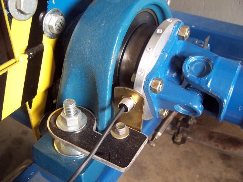
The load arm on the PAU measures exactly 14 inches.. I built a second 14 inch calibration arm on the opposite side of the PAU. The idea is to apply a known weight to the calibration arm and tweak the amplifier (if necessary).
The loadcell is rated for one kilo Newton ...that works out to 224 pounds in dog years or something like that. Metric weights don't make any sense.
Just for giggles, I weighed myself on a UPS scale then climbed a ladder and stood on the calibration arm. Close enough. I figure I can eat 100 more Big Macs and I will weigh enough to full range the load cell or I need to buy a calibration scale. Decisions...
Anyway, the real calibration will be done at some point but for now I'm happy the load cell and amplifier appear to work. Due to the 14 inch load arm, the actual torque generated by the PAU has to be multiplied by .86 to convert to foot pounds. This is just one line of code and never has to be an issue.
At this point I had enough stuff cobbled together to do some basic testing. Getting all the ducks in a row is about as complex as launching the space shuttle but I managed. Long story short, it all works!
With the engine running I can dial in a load and advance the throttle electronically. So far I'm at 65 lines of bullet proof code.
The next step is getting the shaft speed sensor sorted out. I have all the parts in stock however this last hurdle is massive and I'll explain when this thread gets updated again.
Let's look at some pictures...
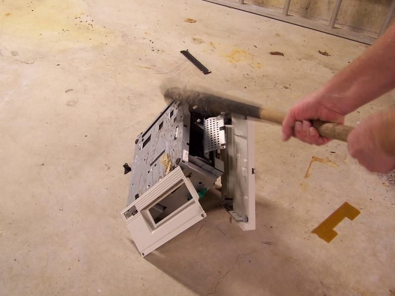 Getting the parts to build the first generation throttle servo. I had to beat the E36 M3 out of a laser printer to harvest the stepper motor and some gears. If you seen Office Space, you know the song....
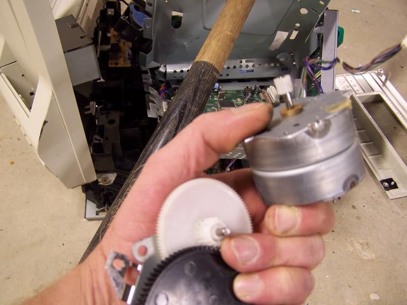 Gears and motor in hand
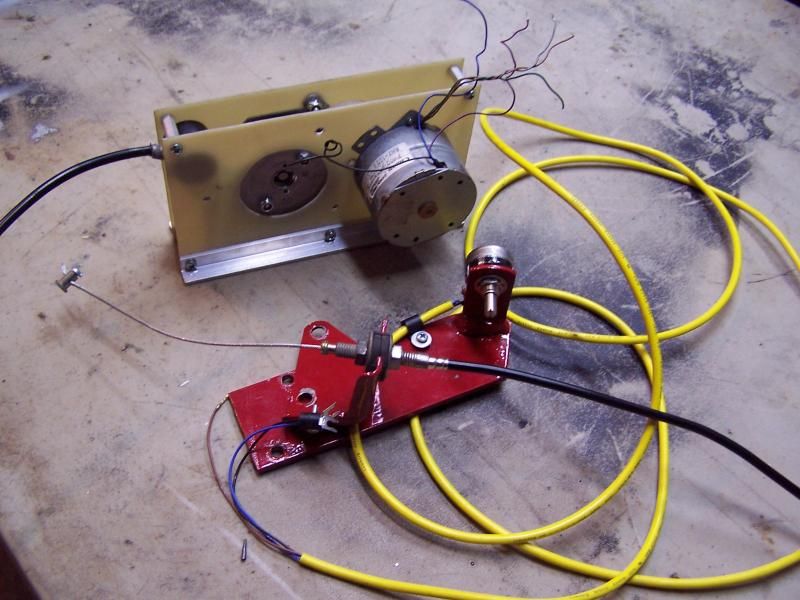 The first generation throttle servo was insanely complex and eventually ended up in the scrap bin.
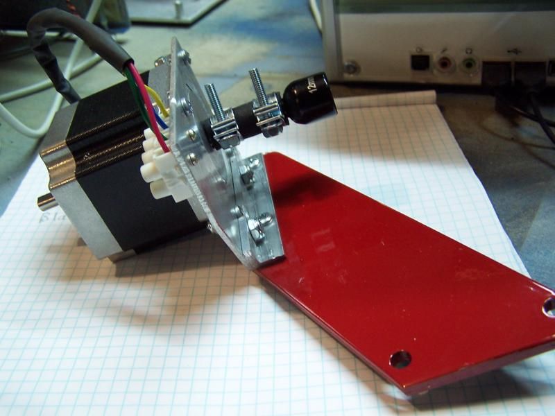 The second generation servo is simple, fast and safe.
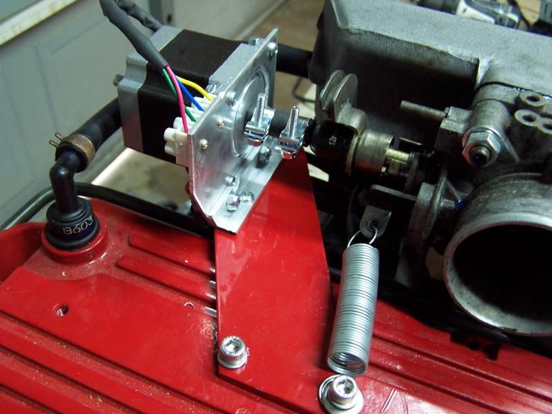 Stepper motor directly coupled to throttle shaft makes life a lot simpler. Flipping a bit in the software will disable the motor controller and the throttle will snap shut in the blink of an eye. Nice!
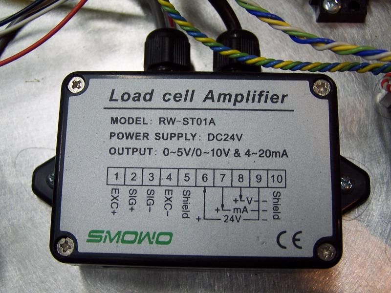 Meh, no drama no surprises. The load cell and amplifier work perfectly out of the box. Five lines of code and it was time to move on.
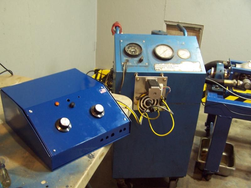 This is the nearly complete dyno controller. The knob on the left is for manual load control and knob on the right is for throttle control. The manual controls are for trouble shooting and setting up the dyno. Flipping a switch will disable the manual controls and a PC will automatically take over.
I'm going to try to shoot some video tomorrow and let you folks get a look at this thing in action.
Stay tuned!


 Next build thread?
 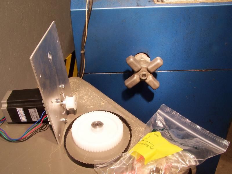 The hydraulic system needs to be converted from manual to electronic control. I picked a heavy duty stepper motor plus controller for $60.00 on ebay. The pulleys and belts were from McMaster Carr.
 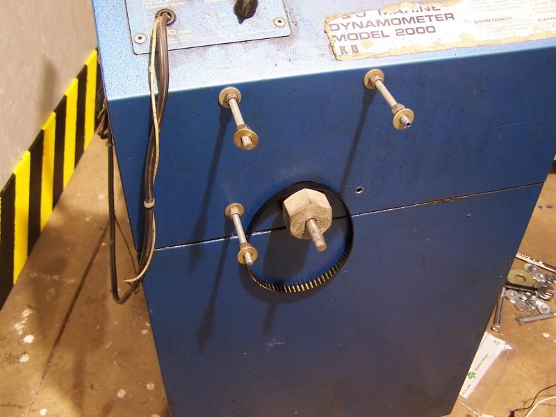 Drilled four holes and assembled some threaded rods to hold the motor plate into position.
 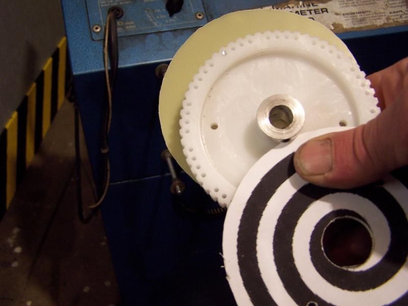 The bottom pulley wasn't flanged so A few fiberglass flanges had to be fabricated.
 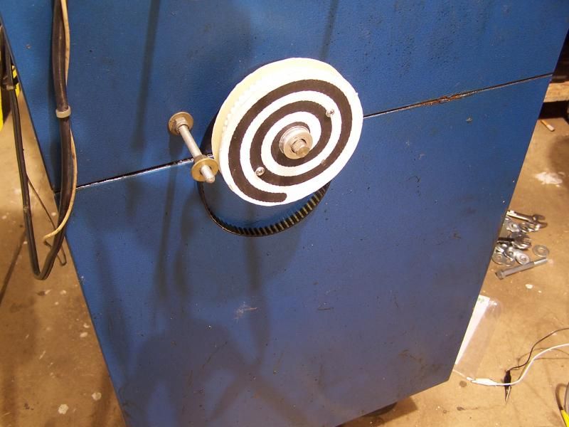 The pulley locks onto the shaft with a set screw. If you stare at the pulley long enough weird things start happening.
 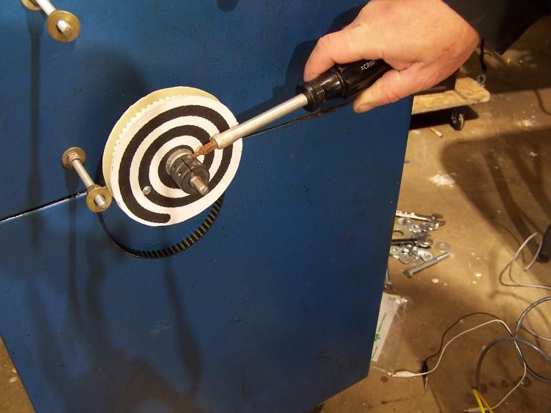 A stub shaft is installed to give the multi-turn potentiometer something to grab on to. The feedback pot is for position reference and for manual control. Eventually the load cell will be used to determine the position of the shaft.
 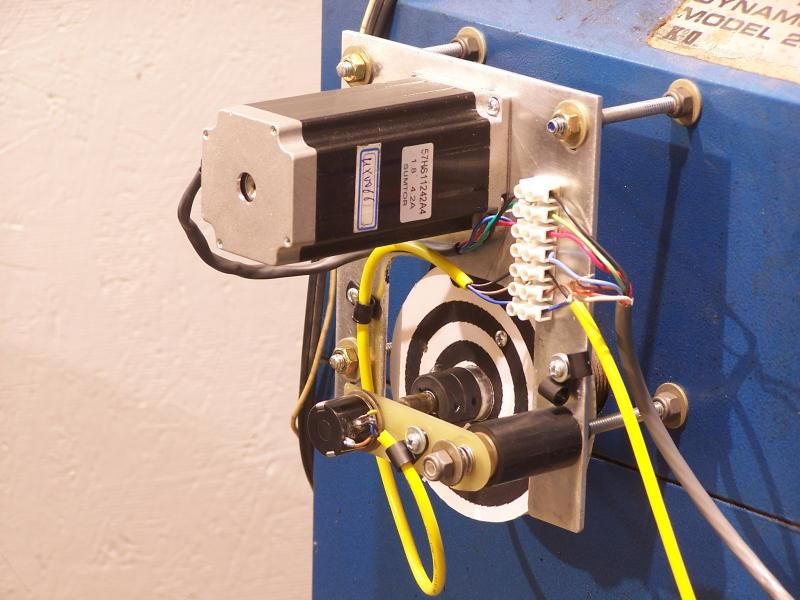 All mounted and wired up
 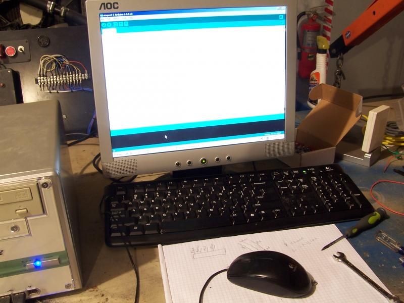 20 lines of code and it woks like a charm.
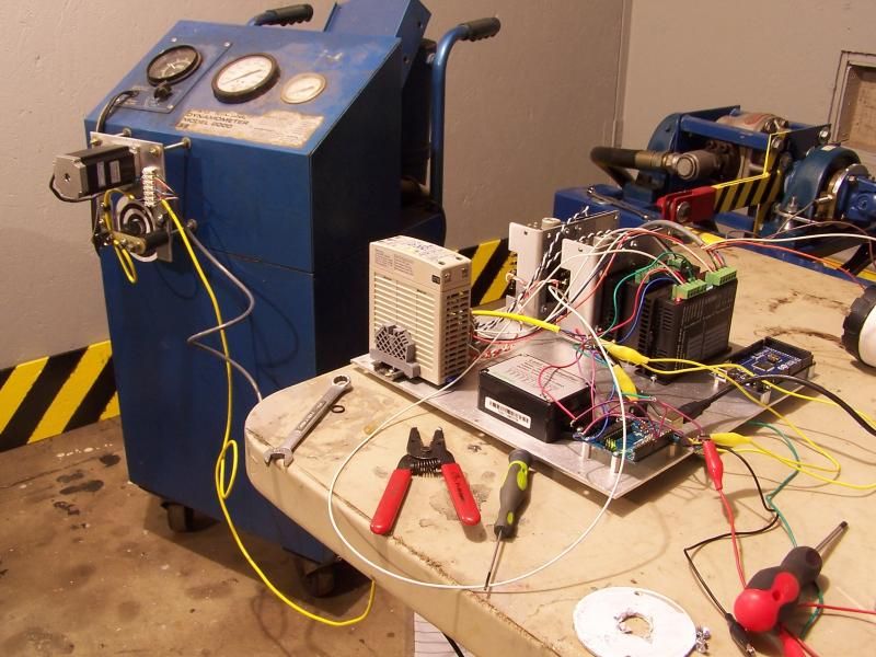 [/URL] The interocitor so far. It features an Arduino UNO, MEGA, load cell amplifier plus two Stepper motor controllers


 Hall effect sensor and magnets was the preferred method of generating a frequency. Unfortunately a slight wobble in the pump adapter made this unreliable. Other methods were tried to get actual shaft speed and ultimately I had to grab the engine RPM signal. A little math in the software is used to correct the transmission gear ratio. The dyno appears to work best when the transmission is in 3rd gear.
 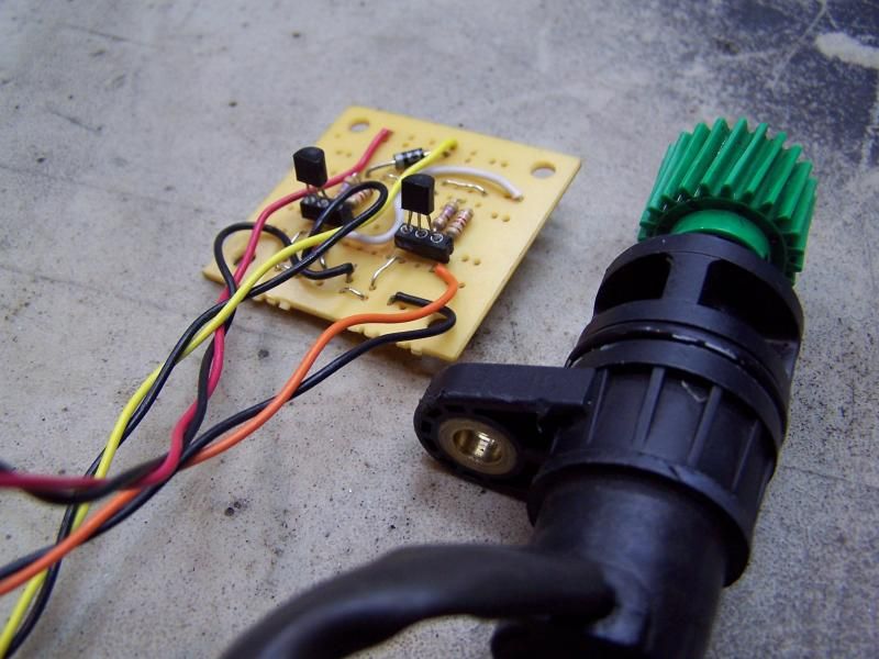 VSS sensor provided a great signal but I wasn't happy with the relatively low frequency I was seeing. The VSS generates an AC signal that had to be converted to DC square wave with a few transistors and resistors. This idea was scrapped as well.
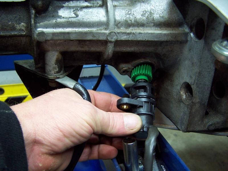 VSS slides into place.
 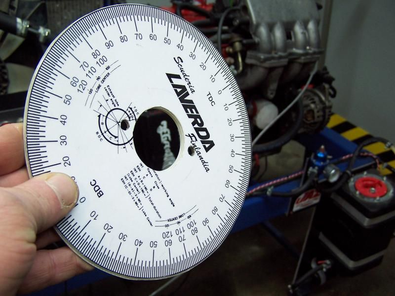 A side project was to make a degree wheel
 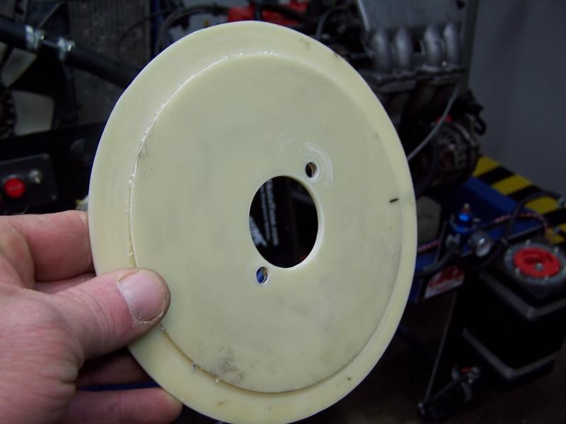 fiberglass, paper and clear plastic makes this wheel indestructible
 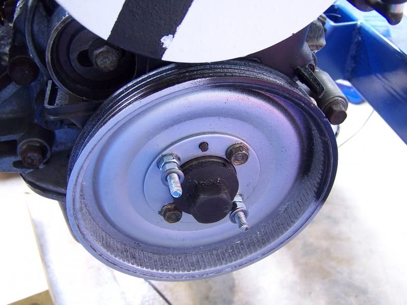 Some studs were added to the crankshaft pulley to support the degree wheel.
 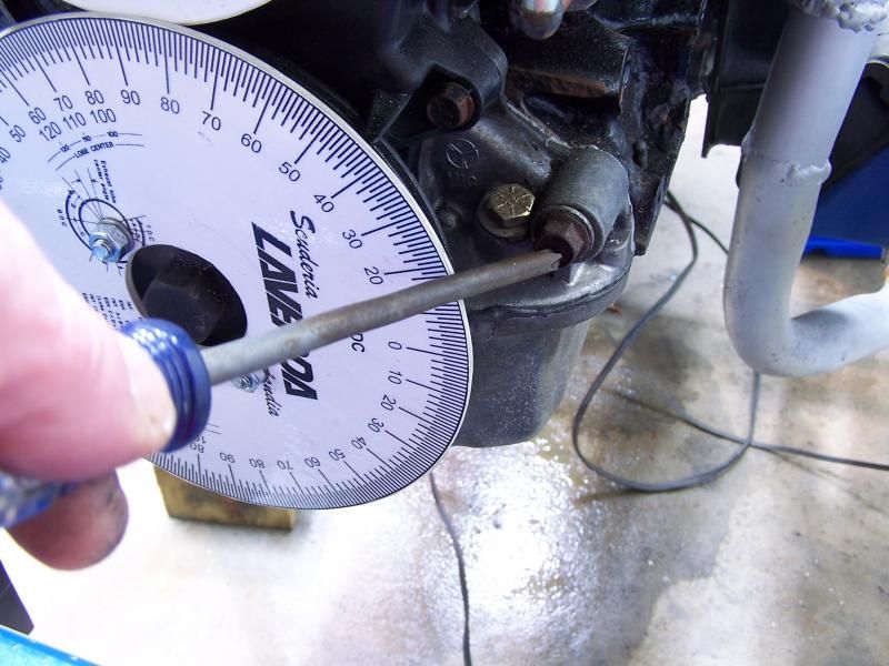 Screwdriver indicates where new pointer will be mounted
 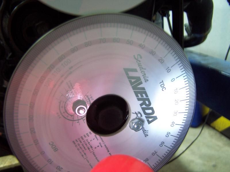 for E36 M3s and giggles I took a picture of the spinning degree wheel. The timing light and the camera works great together.
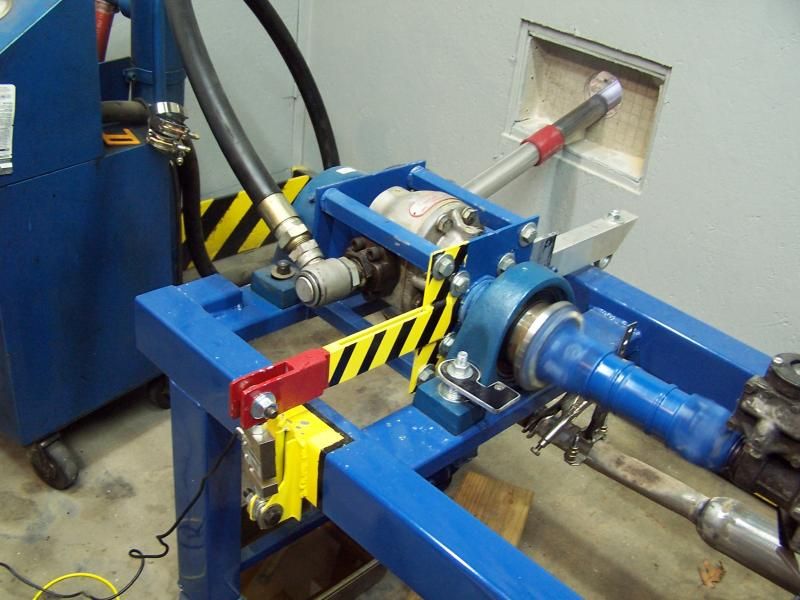 So... we now have shaft speed and torque.....the next picture is the money shot.
 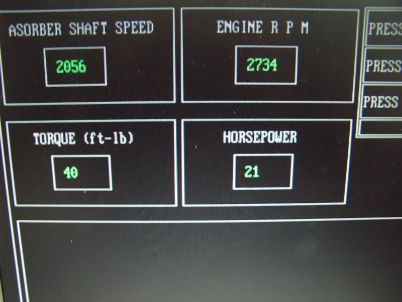 ^^^^THIS^^^^
 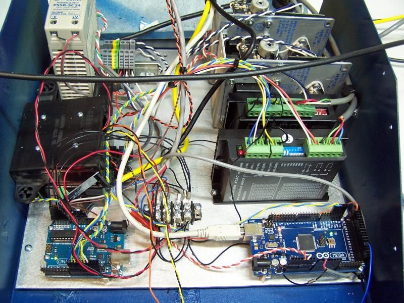 Ten pounds of E36 M3 in a five pound bag. The electronic junk will need to be re-packaged into a larger enclosure.
 queue up the Mission Impossible theme music
  The old enclosure was too small for all the crap. Time to rebuild it.
 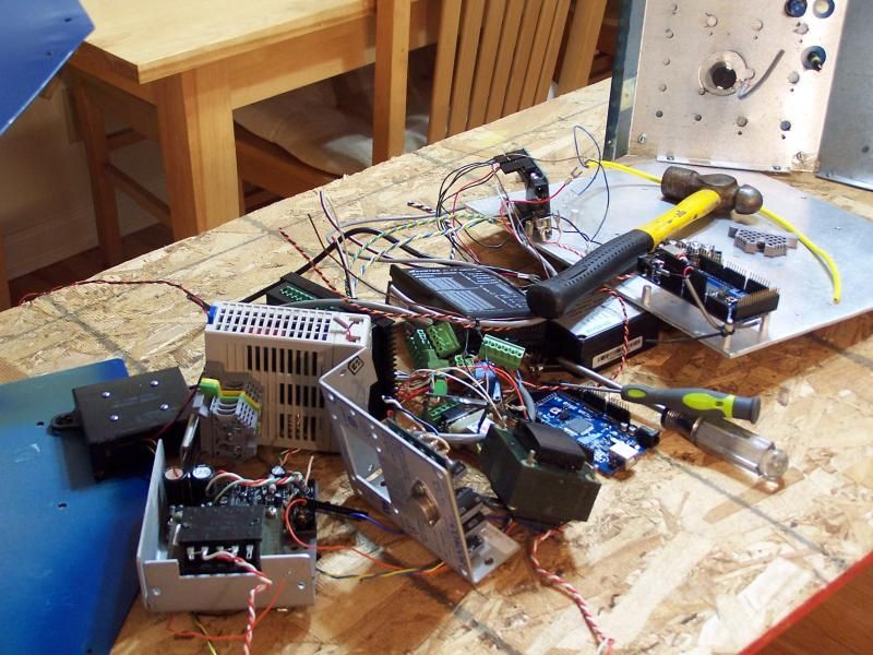 OMG... what have I done...
 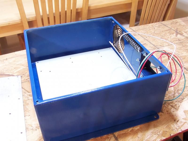 This is the new enclosure... well sort of new. I rescued this box from the scrap pile and gave it a fresh paint job.
 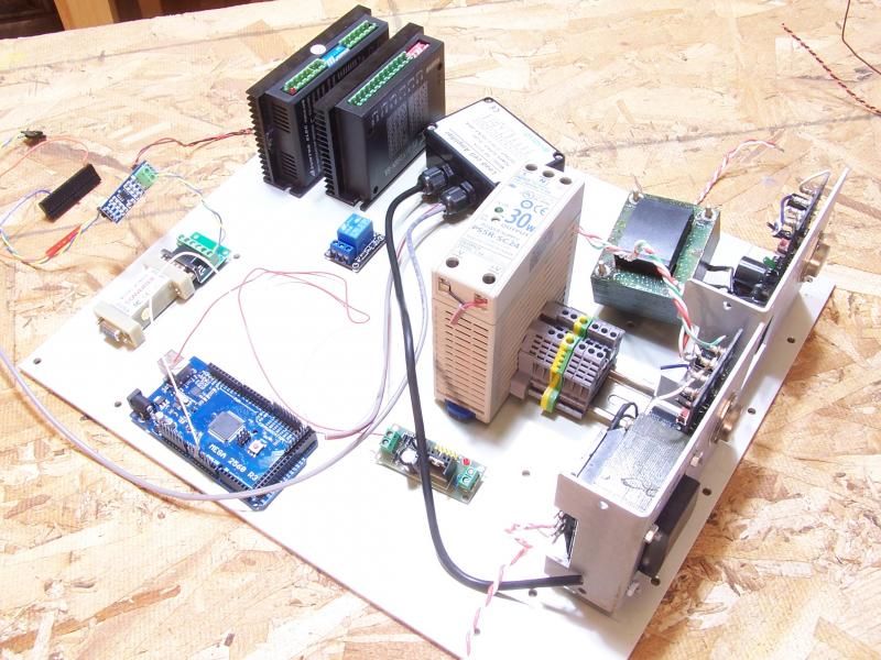 Parts laid out in a semi logical order. This new controller will have two Arduino 3560 micro computers plus a bunch of other stuff.
 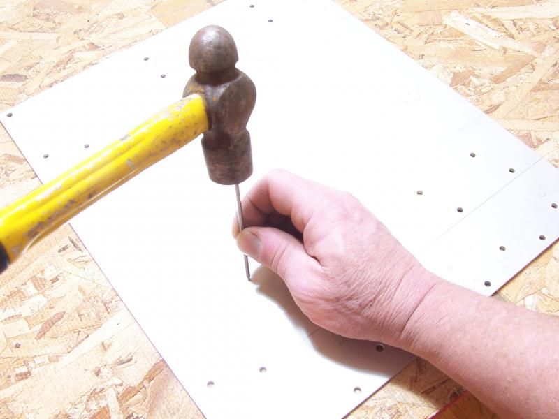 Once the lay out was complete, it was time to put it all together. Here is a MacGyver quick tip. You can make a awesome centerpunch from a stainless steel rod salvaged from any CDROM/DVD drive. Before you toss your busted drive in the trash, open it up and grab the rod. You will need to chuck the rod into a drill and dress it on a bench grinder. The point will stay sharp for hundreds of uses. Try it!
 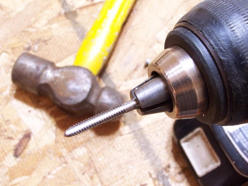 This is a great way to bust a tap. However, if you set the clutch just right and fiddle berkeley the forward/reverse switch... you can tap a bazillion holes in record time. Takes some practice but this is how I roll.
 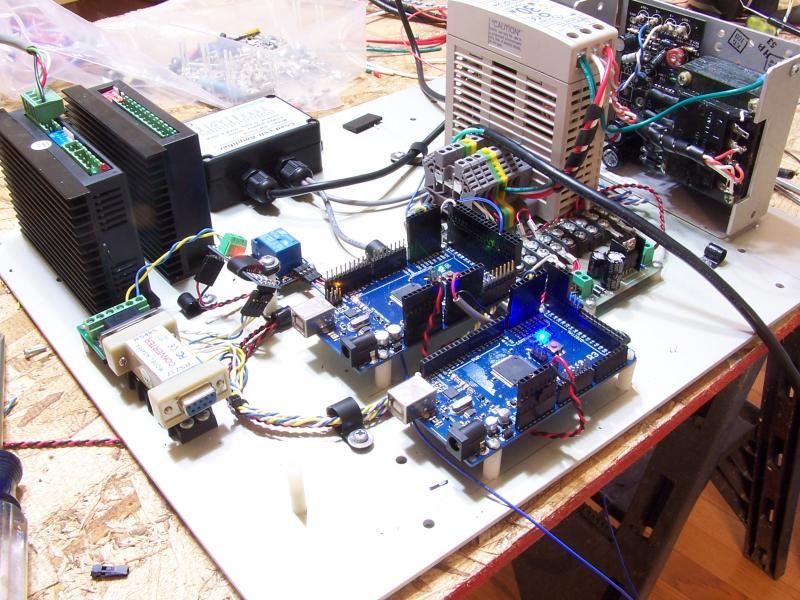 This is where I was after five hours. The basic system powered up with no smoke. yippee ki yay.
 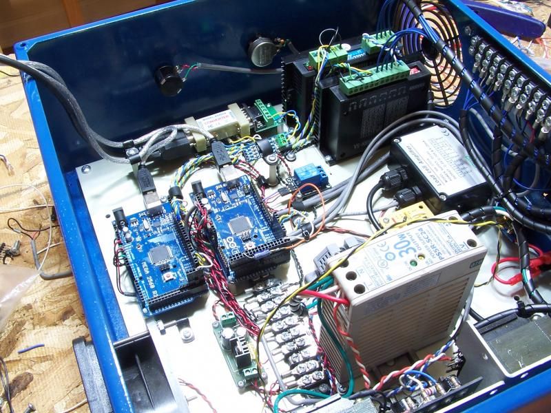 At the ten hour mark, 90% of the wiring was done.
 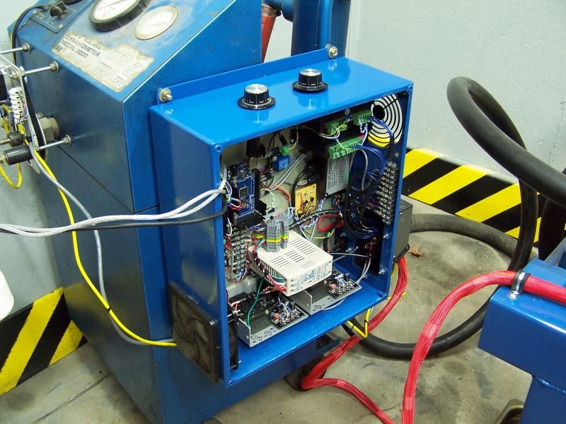 Day two, the box was mounted to the hydraulic tank. The dyno harness was modified to plug into the box and all that was left was to throw the power switch. No smoke, but no workey..Oh, that's right I need to flash the new Arduino with some code. A little while latter the upload was done and to my amazement it all worked.
 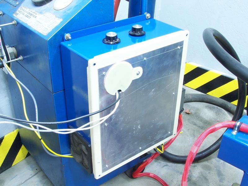 The cover looks like this. It will need some paint to look pretty, but for now it keeps the junk covered.
 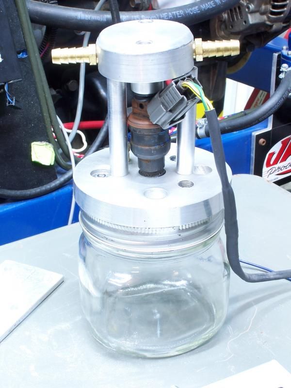 .... And now for something completely different. This thing was formally known as Mr. Fusion. I took the crazy out of it and now it is just an injector that squirts into a mason jar. This is going to be used to calibrate how much fuel is actually being used. It is electronically coupled to one of the real injectors and through a convoluted process I will be able to measure exactly how much fuel is being used. We'll revisit this soon.
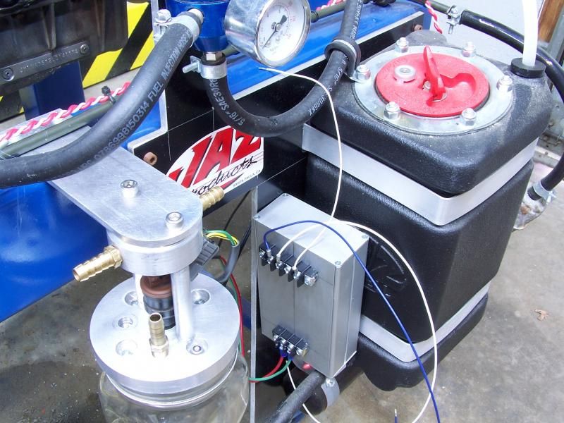 The device formally known as Mr. Fusion is mounted and is awaiting some plumbing.
  Ho Ho Ho.... Santa brings gifts to the dyno. This is a 100 pound digital scale that will be used to verify the load cell is reading correctly.
 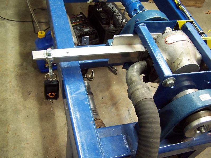 The scale hangs on the calibration arm and is pulled down to put weight on the load cell. According the the scale the load cell is a few pounds off on anything less than 15 lbs, but the loadcell appears to be measuring the correct load all the way up to 80LBS. I wasn't able to get past 80lbs because this is really hard to do and I need to MacGyver something up. The good news is the loadcell is putting out reliable numbers.


