cc454 said:
Honda has a cam sync that plays plays a big roll in its timing paradigm. The tec3r needs it to provide a sync to be fully sequential fueling.
 The honda has two sensors and 4 timing pulse each, some degrees apart. I just need one. I need to call Electromotive and see if the ecm will just respond to the edge of the 1st pulse and ignore the rest, or do I have to do some mishaniganse to make it output a single pulse. Simple to machine off all but one of the teeth and use only one of the sensors.
The rest of the sensors are pretty straight forward, I just need to swap GM for Honda and I'm cool.
You definitely need to grind off the other three teeth. One cam tooth is all you need, and any more will just cause your ECU to error out.
Curious that the Electromotive wouldn't allow you to use a 24 tooth crank wheel. It's a configurable setting in most any ECU I've ever used. I assume with that 60 tooth wheel, you're using a VR sensor. Was the original sensor VR too?

cc454
New Reader
6/30/20 7:29 a.m.
Mezzanine said:
Curious that the Electromotive wouldn't allow you to use a 24 tooth crank wheel. It's a configurable setting in most any ECU I've ever used. I assume with that 60 tooth wheel, you're using a VR sensor. Was the original sensor VR too?
VR? Variable Reluctance? I'm not sure what type of sensor the Honda unit was, but its the same as the cam sync, It's also about 1/2" in diameter so I'm betting it would have trouble seeing the fine pitch of the 60-2. The sensor is listed as:
"3/8″ chisel point magnetic sensor for use with all Electromotive systems. The 3/8″ chisel point sensor features a fine chisel point exposed sensor element for use with small-diameter, fine-pitch trigger wheels. It should be used with 60-2 trigger wheels under 3″ and all camshaft speed wheels. It can also be used to replace early flat"
Variable reluctance (VR) sensors are commonly used in a form factor that has a 1/2" wide face, but it reads close teeth just fine. Hall effect sensors on the other hand definitely need only one tooth crossing the face at a time to function correctly. I made this mistake in a build recently, choosing a hall sensor since it has a lot of great qualities, but not choosing a trigger wheel that would suit the form factor of the sensor.
You should be in good shape using what they recommend.
cc454
New Reader
6/30/20 5:36 p.m.
I'm going to mock up the honda sensor and see how it looks on the scope. It would be great if it did.
cc454
New Reader
7/2/20 6:30 a.m.
I am trying another set of seat rails from a Fiero, that are a little over an inch tall. I wanted to get a little lower then the electric seat rails.
Mounting the vette seat to the Fiero rails required a small extension to bring the rail to the seat's mount. The floor mount holes just needed a little slotting, so it would be possible to swap between the two kinds of seat rails.
cc454
New Reader
7/2/20 9:31 p.m.
I did a little massaging on the fiero rails. Mostly adding some length and a little offset on the right hand rail.
Once I got the topside fitted the bottom side was easy to fit to the floor,
The electric rails left the seat bottom about 3", the fiero rails high spot is about 2".

The seat frame is just about even with the door sill.

You can see now how low the seat bottom is relative to the door sill.

Now I'm pretty sure my helmet going to fit under the bar. The top of the door hits me right on the scapula, so no hanging my arm out the window. I also found out that I can't close the top with one arm either.
Did a short ride and I think it is a big improvement, need just a few tweeks and a little work on a control panel for the seats.
cc454
New Reader
7/4/20 9:23 p.m.
I worked on getting the passengers seat in. Rather then using a slider I used a fixed bracket to get it closer to the drivers height.

Don't mind the dirt and leaf crumblies. The car has been outside for 2 years near a live oak. Again I love the way the vette seats bolt together.

You can campare the driver side to the passenger height, with the fixed bracket it gets pretty close. Much better the the sliders 2+ inches. So I'm thinking most passengers will pass broom stick too.

Few things left to do like put seat belt receivers in the right spots on both side. But the seats feel great and look really good in the miata to me.
cc454
New Reader
7/5/20 6:21 p.m.
Relocated the seat belt receivers to a more comfortable positions on both sides. Decided to put in the lowest fixed bracket on the drivers side to live with it for a little while.
I basically have the seat mounted on the interior side of the frame rail.
Now my shoulder is below the door opening.

Now I got plenty room for my big nogan bucket!
cc454
New Reader
7/8/20 5:39 p.m.
Got a little ride time with my wife in the new seats. I was wondering if she would like them. (She hates the car) Well,,,,,,,,,,they Are better then the original seats but she did not like the fact they wore fixed and her feet were about 6" away from the fire wall. She is almost a full 5 feet tall.
Also the car rode like crap after being on jack stands for 2 weeks. Like it was on the bump stops. It was the 1st time I have had a passenger since I rebuilt the suspension and my 1st thought was I didn't have enough spring for the added load. (I was not going to say that to my wife) It did get better after a few miles.
After getting her input I went for a more normal spirited drive alone this time. I had to get used to the big man mod to the gas pedal I did, but the car felt good and the new lower seat position maybe a touch too low for me. I feel like the steering wheel needs to come down a little too. I will see what I can do with the colum mount and ride with it some more.
The real big difference in the car was that I had to remove the door bars to fit the C4 seats . And then add the new frame rail braces underneath. My best testing spot was too busy to test at. I will have to work out something to mount the bars back on the main hoop with out cutting the plastic seat back shell and losing structural strength.
cc454
New Reader
7/10/20 5:23 a.m.
In the mean time I cleaned my garage to clear a spot for the engine wiring and final assembly. With it on the Minitech subframe I can still access the starter install.
cc454
New Reader
7/12/20 4:58 a.m.
I picked up this coolant pipe on ebay, not sure of which version of the J series engine it comes from, but its one that might not have a heater. There's not the typical small tube for the heater.

Honda made this end of the motor the busy side which most of is bypassed, blocked or moved somewhere else. I simplified things and left the thermostat loose from the motor untill it's in the car. Most likely it will be mounted to the firewall.
I may forgo the AN fittings and just run hose barbs for lightness. I think the Miata fuel system has a return from the regulator run off. The Honda system looks single ended by the way the plumbing is laid out on the fuel rails. But I'm missing the oem fuel regulator that's mounted on the back of the right head.
cc454
New Reader
7/13/20 12:32 a.m.
The Electromotive Tec3R unit is a pretty sweet control unit. One of the big pluses is it's high resolution timing of ignition events with its 60-2 tooth trigger wheel. It would be great if the Honda sensor would be compatible with the Tec3R electronics, but alas, no bueno. Looks like the Honda sensors are variable reluctance devices that are driven by an excitation signal from the Honda ecu.. The tec device is driven by a TTL binary signal by the sensor by itself.
This means I have to fit the Electromotive sensors to the crank and cam trigger. The crank is pretty easy but the cam sync needs some looking into. There not much space under the sprocket.
The temp sensors will be GM as well as the MAP sensor. The Knock sensor is the Honda unit for this motor because of its tuning. I have not figured out what I will do for the IAT servo yet.
cc454
New Reader
7/15/20 10:10 p.m.
Since I've done away with the big water manifold I found the drain plug on the drivers side to be a pretty good spot. I tapped it for 3/8 pipe for the the GM's temp sensor but I didn't realize the one I had was metric threaded. So got to get another one.

While I'm waiting for parts to arrive I got back to the door bars and measure the interferance zone on bothand cut them out.

I filled the area back in with 3/16 plate and welded them back up and ground them smooth. Ready for paint.

The next part will be addressing the thin sheet metal that the front half of the door bolts to. I'm going to make larger mount pad with some vertical elements, and weld it in.
cc454
New Reader
7/16/20 8:40 p.m.
One of the parts I'm missing was a flexplate washer. The bolts and flywheel spacer come from MiniTech. I'm using the correct B series clutch and flywheel but a non-typical model. Any how the bolts are a tad bit too long and some bottom out pretty bad before getting close to the clutch surface. I'm hoping the was is enough to get the binding length right.
I still had to re-dress a few of the bolts to shorten them up but finally got a good bite on the flywheel and ready to marry the clutch pack.
Finally got everything torqued up and looking pretty!
So now I'm good to about 800 ft lbs of torque. What I like is its small diameter and mass. I can't wait to see how it feels and shifts.
There is some awesome work being done on this project. Really impressive! It's gonna be sweet.
cc454
New Reader
7/17/20 8:02 p.m.
Vigo (Forum Supporter) said:
There is some awesome work being done on this project. Really impressive! It's gonna be sweet.
Thanks!
Today I re-installed the door bars after making some some new mount pads for the front side. As they were they were just mounted by sandwiching a single thickness of floor pan next to the side rail. I want to weld a 3/16" plate pad to the floor and add a 1" vertical strip to weld to the rail and tie everything together. But I ran out of metal to make the 2nd one. I did just bolt them back on and took a test spin. This was a first with the door bars and chassis braces. I can tell it's nice and stiff now. I really need some track time to start sorting out all the new frame stuff.
cc454
New Reader
7/18/20 4:02 p.m.
The 1st pic shows the problem of just mounting to the floor board. It's really thin.

So the idea is to weld a pad to tie it into side rail and still be a bolt on.


I'm going to add another inch on the vertical part. Unfortunately I'm almost out of shield gas

On the bottom I made a bigger backing pad to cover some double skin parts of the floor.
cc454
New Reader
7/18/20 4:19 p.m.
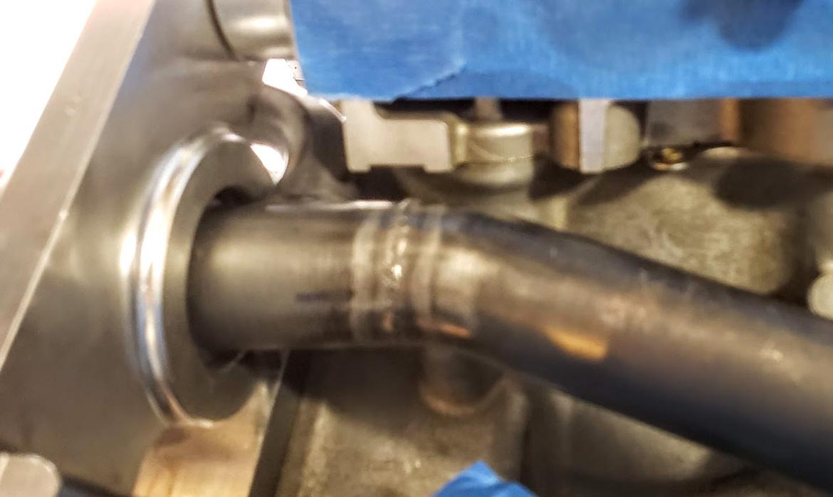
The other water pipe came in and I'm going to re-work it a little so that the heater core return water hose makes a graceful entrance back into the water pump.
As it is now is stage exit right when it should be left to the heater core.

I'm thinking if I cut the water pipe on the dotted line and rotate it about 180 degrees and butt weld it back I can get it going in the right direction.

I can feed it through this area were my finger is (after a little clearancing)

The hot water side to the heater core will come from the remote thermostat housing (before the thermostat) with a manual shut off. So I don't have to roast my feet trying for some air flow.
cc454
New Reader
7/19/20 5:22 p.m.
Got the heater core return sorted out. Cut, grind and check fit. I do need to double check in the miata where the inlet to the heater core is relative to the center line of the car to see if I'm going to move it one more time.
 Just need to tig it back together.
cc454
New Reader
7/19/20 5:29 p.m.
I dug out the wire harness stuff and checked the fit of the 3/8" crank sensor in the oem spot. No Bueno. It's too long to fit where the factory sensor lives. I can mount a trigger wheel to the damper and have it external. It might be safer to have it easy to get at as they are known to fail every once and a while.
cc454
New Reader
7/21/20 9:18 p.m.
Got the water pipe welded up and figured out the hard line should end up under the heater core outlet. So I will leave at that until engine is married to the car.
Spent the rest of the afternoon cleaning and rebuilding the valve covers. Cleaned out as much of the calculus from the nooks and crannies from the underside and replaced all the gaskets and grommets.

I went with an emerald green hammer tone for something a little different. I also went with a set of covers from an early 30a1 distributor motor, they have less lumps and tapped bosses for COPs, The Electromotive Tec3R ecu uses their own wasted spark coil pack so I'm running plug wires on this.
cc454
New Reader
7/23/20 6:05 p.m.
I put on a better top today replacing my leaky, worn out original top with a good looking aftermarket one with repaired L shaped spot on it.
It did not look too bad laying there on the ground at the swap meet. But after installing the top the repair is right smack dab in the middle of the B panel. Like a big loser L tattoo.
I need to find those flat stainless rivets so I can re-install the OEM gutter .
At least I now have the parts to make my bikini top for the car.
Started in on the test of the tec3R ecu and then the sensors. Gathering parts.
cc454
New Reader
7/28/20 2:53 p.m.
I was rummaging around my exhaust bin and came across these 5" Super Trapps from way back and the un-opened replacement cores. I got to thinking about a center exhaust and what would it sound like. They were already paired up and slipped onto a steel 3" exhaust. also had some left over 3" donut quarters and a Cast stainless flange that would match the Miata's existing mid-pipe.
Added a center hanger through the bottom of the spare tire well and fabbed a S-pipe and was good to go test.

I tried the SuperTrapps with no cores and it was pretty loud for just the resonator and a coupla megaphones, It was real deep sounding though. I added the perf-core and disk packs and it was almost like the cores were not there at all.
Next I did one with stainless packing and the other with the fiberglass packing. I like the volume but it had a annoying drone so I replaced the fiberglass with a different stainless mesh and I got rid of the drone but it's almost as loud as my race muffler. As it rises in rpm the tone changes harmonics and thins out a bit.
I like it
Plus they look ridiculously huge under the miata. have some vintage 4" single nut units that would look a whole lot better but no pipe to make something. The big turbo muffler still would be my pick but I'm going to leave this on for a few days to proof it out.
cc454
New Reader
8/9/20 7:04 a.m.
I'm still running the big SuperTrapps, The tone grows on you. :) Too bad its just a tad loud for what I'm looking for in this car. Started gathering exhaust parts to build the V6 headers and 3" exhaust system. Thought I'd do the engine to through the frame part while its out and then get the cat back to down tubes when the engine is in the car.
At this time I got the new intake manifold some what sorted out with a linkage setup. This probably needs its own post about 3D printing your own custom intake manifold.

I still need to run some motion sims to make sure I get the right amount of blade rotation to Miata throttle cable travel.
On other news I got some day gigs to work (Thank goodness!) so I can get this thing printed out soon.
cc454
New Reader
8/23/20 4:59 p.m.
It's HEADER TIME! Prices for mandrel stainless bends is crazy too much! If I bought what I needed the headers would easly be over 5 big ones for materal. I went through my tube left overs and gathered up what I could use and found I had 2 discarded headers that were the right tube diameter.
Since the cheapy ebay headers I had purchased for an accord turbo setup started with 1 1/2" primaries and I have a 2 1/2"-3 " y-pipe I would do a stepped header to make /it work with what I got. So it will be 1 1/2" primary to the 1st bend, then step to 1 5/8" to the 2nd bend, and finally 1 7/8" to the merge collector. Then 2 1/2" to the y-pipe.
I have a 3" metal matrix cat that everything goes thru then down to the rest of the exhaust system.

I think I will be short on 1 7/8" tube. Need to see if there is any at the motorcycle scrap yard.

I need to bolt in a A/C compressor and a alternator and see how much space I have left.
 I would like the collectors to end up some where around here.


