1 ... 13 14 15 16
Patientzero
Patientzero Dork
10/3/23 10:10 p.m.
GCrites said:
KentF said: So, the guy in the video was using an oscilloscope. Remember the oscilloscope? I bought an oscilloscope for $120. Have not used one in 40 years. They used to have cathode ray tubes and were the size of a restaurant coffee machine.

Haha, I totally thought they were still like that.

Some still are, I guess they have a grassroots friendly version now too.

KentF
KentF Reader
10/6/23 7:30 p.m.

Jacking Rails

Last Christmas my #2 son got me a $50 gift certificate to Summit. So, I bought some $80 Jacking Rails. Been wanting this for years but never got them. Last spring while waiting for other parts I installed them.

You are supposed to weld them into the floor pan and the raised seam. This would require dissembling much of the interior so as not to set fire to it. I was still recovering from a knee replacement and did not feel up to that much climbing around inside the car.  The rails came punched with 5/16” holes every six inches. Yes – it would be stiffer and better if they were welded. My goal here was to make the car easier to jack up at an event. I bought bolts…

First order of business after removing the plastic rocker covers was to fix the damage to the raised seam holding the body panels to the floor pan. Years of raising the car with various jacks and shop lifts had left its toll. Much of the damage was actually done by mechanics who did not pay attention to the exact placement of their equipment and did not have lift pads with grooves.  I remember coming back from some crap @#$% mechanic and discovering part of a seam had been perfectly flattened. The car was still new then! Come-on man! I never went back to that shop.

In later years it did not help that the Spintech side exhausts make hitting the rear lift points more difficult. It is almost impossible to get a jack and a jack stand in that small space. Since putting  sub frame rails on several years ago I have avoided using the OEM lift points because they were slowly crushing up into the body of the car. They are made to support the car at these specific positions. But just barely. And if you flatten them they have no strength at all.

After a lot of hammering and pulling and a little cutting I had the seams fairly straight. I then primed and painted everything and finished if off with black truck bed spray. Luckily this car has not been driven in winter for several years now or all of this would have been rotted out. The metal is still good, just a bit bent up. I also sprayed the frame rails with truck bed spray.

Next came drilling through the pre-punched holes in the jacking rails through the standing seam joint. This was a bit tedious and awkward since I still could not fully bend one knee. Then I started wrenching them together. The strong straight jacking rails pulled in the body seams nicely. They never looked better.

Now the plastic rocker panel facia. It also was bent and permanently deformed by abusive lift management. Nothing a heat gun and some wide face pliers could not fix.

This turned out to be a much more rigid assembly than I expected. Yes, it would be stiffer if welded. But the bolts really pulled together the seam and got it back to the original engineered shape.  And no more damage from sloppy people with lifts.

Mustang50
Mustang50 Reader
3/7/24 12:25 p.m.

Kent:  We haven't heard from you in 5 months.  Are you and the family OK?   Any new updates on the Mustang?

KentF
KentF Reader
3/7/24 4:34 p.m.

In reply to Mustang50 :

Hi Mustang50. We are doing OK thank you for checking. I had the last post written (in the can so to speak) and then published it from the hospital. I had my wife proof it because i was on some "pretty good" pain killers at the time.

I had a bad infection in my left knee. Long recovery but doing fine now. Pretty much October through mid December were a lost cause. 

Have gone to part time at work and liking it. Mistress almost has a new radiator and I just finished replacing all the mangled brake lines. Will have that all written up soon.

The Radiator turned out to be a lot of work! Currently it is removed (again) to make access to the brake lines. Now that that is done I can do final assembly. Some progress photos below.

So how are you doing?


rdcyclist
rdcyclist GRM+ Memberand HalfDork
3/7/24 6:18 p.m.
KentF (Forum Supporter) said:

It is a ratcheting cable clamp that opens/closes the spring clamps on hoses. Works great. $50 at NAPA. Hose Clamp Tool

They're 92 bucks now. Dammit.

KentF
KentF Reader
3/7/24 7:29 p.m.

In reply to rdcyclist :

Ha! Keep searching.  I am seeing a lot of very cheap versions (too cheap junk) online. However, this one  looks better than mine for $64:

Lisle 17300

rdcyclist
rdcyclist GRM+ Memberand HalfDork
3/7/24 9:34 p.m.

Thank you for that! Yes, Lisle tools are pretty good. I've not broken many of them over the years so I'll get that one.

Mustang50
Mustang50 Reader
3/8/24 12:16 p.m.

I'm doing OK health wise.  But a little depressed over my decision to cease auto crossing due to heart issues.  I still love driving my Mustang.

KentF
KentF Reader
3/18/24 9:33 p.m.

In reply to Mustang50 :

Hang in there Mustang50. I learned one of the secrets to life is how we "let go" of things we love. I have not mastered it either.

KentF
KentF Reader
3/18/24 9:41 p.m.

New Radiator - Part 1

I used to be cool. Then I had kids. The kids grew up. I got a little bit of cool back. Just a wee bit. It is harder to be cool when you are old.

My car, however, has only gotten hotter. And that is cool. This summer Mistress got so hot I could not keep it cool and had to delay some runs while I frantically used the tire sprayer on the radiator and intercooler. That was not cool. And it is not fast either. I already hold the car back. Even more so if I spend time between runs thinking about the car rather than where I left some time out there.

To get through the summer I switched out the coolant to Stay Frosty water-based coolant (water has better heat transfer than glycol). I also removed the air conditioning to allow better air flow (never use it anyway).

The little OEM single pass cross flow radiator could not keep up with the additional load. So… How much radiator do I need?

I started writing up a Long Sciencey physics answer to that question with heat transfer calculations and such.  Then I realized I could not “close” the discussion because I had no actual data on temperatures and fluid flows.

So here is the intermediate answer:

 For any given “system”: Energy Out = Energy In + Energy Stored. For this discussion I am defining the “system” as the engine in Mistress with the fuel line as “Energy In”. The Radiator, Exhaust & Crankshaft are “Energy Out”. We are going to assume the car is all warmed up, battery is charged up, etc. Therefore, Energy Stored is roughly zero. We are also going to hold this discussion to full throttle maximum inputs and outputs. Basically like a dyno run.

Energy Out: From the factory the engine in Mistress was rated at 193 HP. That is the mechanical power (energy/time) coming out of the crankshaft. That can be converted to more universal units of kilowatts or 144 kW.  Today, I estimate the supercharged 4.2 ltr version of that engine generates about 390 HP or 292 kW.

Reference Point: In the US, a 120 VAC household electrical outlet can supply about 1500 Watts or 1.5 kW. So, the engine in Mistress can create about the same power as 292 / 1.5 = 195 electrical outlets at full throttle. Get some extension cords…

Energy In: A modern automobile engine turns about 35% of the chemical energy in the fuel to mechanical power.

Hold on – If you google that you will find numbers more like 20% to 25%. Those lower numbers include the whole car with losses from the drive train, tires, wind, etc. We are interested in waste heat from just the engine (the “system” defined above, not the whole car). If you google the energy efficiency of an Otto Cycle Engine you will find a lot of serious calculations and deep study papers.

After a lot of webbernet gleaning you may find that the ideal efficiency of an Otto Cycle engine with a 9.5:1 compression ratio is around 55% to 58%. That ideal engine is not real and exists only in spreadsheets, graphs, and physicist’s dreams. In the real world of steel, aluminum, inertia, friction, combustion, and heat transfer the things are about 20% less efficient than “ideal”.

So – Let’s, say Mistress turns 55% Ideal – 20% = 35% of the fuel energy from the fuel line into mechanical power.  But the engine in Mistress was designed in the late 1970s. It barely qualifies as a “modern” engine. Let’s round that down to 30% efficient for this exercise. So -30% of the energy in the gasoline comes out the crankshaft.

Working the math backwards the 144 kW original factory output would require about 144 / 0.30 = 480 kW of chemical energy in the gasoline. Today the estimated 292 kW of output would be 292 / 0.30 = 973 kW input from fuel.

Wasted Energy Out: The original wasted energy was about 481 kW – 144 kW = 337 kW. Today it is 680 kW.

More interblag gleaning will likely net you that the wasted energy on an Otto Cycle engine is split at about 40% exhaust and 60% radiator. This works out to 202 kW of radiator heat rejection on the factory engine and 408 kW today. So, I need a radiator that will reject in the neighborhood of 408 kW of heat energy. That is equal to 272 plug in 1500 W electric heaters.

It makes sense in that, all other things equal, the available power at the crank has increased by a factor of two so the heat rejection has also increased by two.  So – I need a radiator that can “reject” over 400 kW of heat from a 202 degF coolant fluid to 95 degF air (a hot day in the Great White North).

As a tangent: All things are not quite equal in this case. The engine at high RPM and WOT is now being fed an air/fuel mixture at around 12 psig (almost two atmospheres). This is a higher energy density than the original design and in physics it is always easier (more efficient) to convert from one form of energy to another at higher energy densities. This engine is more efficient than the original.  On the other hand, most, if not all, of that efficiency gain is lost again by the parasitic losses running the supercharger. We have more power, but not more efficiency (still ~30%).

All of the above is theory and rough numbers. Your mileage may vary. Mine might also.

The Short Answer to how big a radiator should I install:  As BIG a radiator as will fit in the damn car! That is what I did. It did not really fit. Width and height and mounting points match but this thing is much thicker (four pass verses the original one pass). This is an aftermarket radiator meant to fit in a 500+ 4.6 SVT.

Mods to make it fit:

  • The supercharger intake duct had to be modified to clear the radiator.
  • The new radiator itself had to have mods to its secondary brackets.
  • The OEM “puller” fan had to come out and be replaced by a “pusher”.
  • Even with the air conditioning condenser removed the intercooler had to move to make room for the fan.
  • The bumper had to move to make way for the intercooler.
  • The dense Styrofoam crush zone had to be trimmed to fit behind the plastic outer cowel.
  • The structural fiberglass framework that holds the headlights had to be trimmed to clear everything.
  • While I was at it, I modified the structural bumper to allow better airflow to the intercooler.

The rework was a little more extensive than expected!

Speaking of the fan: The tune for the car has a low speed and high speed temperature settings. I have always gone for about 202 and 212 degF. The GT has the same fan (they are interchangeable). However, when rewiring the fan I discovered only two wires in the harness to the fan (the fan plug has three wires). Going through the wiring diagrams I found that only the GT has the high-speed circuit. But the programming is still there! And the high speed windings are in that fan. They saved a relay and a wire on the V6 car.

That is the set up for what I have been doing all winter. Next posting will run through the details step by step.

More to come...

Mustang50
Mustang50 Reader
3/19/24 12:36 p.m.

WOW!  That analysis was way beyond my ability to comprehend.  Please allow me to ask a stupid question.  What temperature thermostat are you using?   When I was autocrossing my V6 Mustang I changed to a 180 Deg. thermostat and that helped my heat soak issues between runs.  My car is obviously not putting out the HP yours is.

KentF
KentF Reader
3/19/24 5:57 p.m.

In reply to Mustang50 :

Thanks. Just messing around. 

I believe my thermostat is 190 degrees. I have not thought to change it. I don't think the extra ten degrees would buy much time on a one minute course and it would still take a long time.to get back down for.the second run. At the rate it was cooling it would take 20 min to get back to 180.

I can watch the temperature on my phone from the OBDII link transmitter as well as the analog water temp gauge. It would be fine unless the air temperature was 80 degrees or more. Then it would take a long time to come down and shut the fan off at 203 degrees. The thermostat is still wide open above 198 or so.

KentF
KentF Reader
3/19/24 6:19 p.m.

More Messing around: A gallon of gas contains about 114,000 BTUs of energy.

973 kW (full power input to Mistress today) is 922 BTU/second.

So at full power Mistress burns something like 922 / 114,000 x 60 = 0.48 gallons of gas per minute. 

Something like a half a gallon per minute. That is why people starting out the autocross day with 1/4 tank are on fumes by the end of the afternoon.

KentF
KentF Reader
3/25/24 8:53 p.m.

New Radiator Part 2 – Cut to Fit. Bump to Suit

The radiator I bought theoretically has four times the surface area as the stock unit. However, each successive “pass” of coolent is downwind of the one before it. The air is heated as it flows through the thing making the last row much less effective than the first one. Also, this car generates more power than a stock GT of the same generation (2 or 3 row radiator). So, as noted before, I went for as much radiator as would fit in the car for about $220. As noted earlier, it did not really fit. Side to side was great. Right in the same mounts on the frame. Front to back: Not good.

Note there is no radiator cap on the thing. A GT has a plastic pressure/overflow tank with the cap on it. Mistress had the cap right on the radiator and an overflow tank down by the fan (old school). I needed to duplicate that arrangement and did not have room for the GT configuration. That is why I also bought a little 1.2 quart aluminum expansion tank with radiator cap mount. More on that in the next entry.

The Intake Cowl

Clearance issues started with the first test fit.  The new Radiator core is 3” thick while the old one is only about ¾ inch thick. The front of the radiator is in the same position but the extra thickness is towards the engine.

The supercharger intake cowl (air filter to supercharger inlet) conflicted with the fragile radiator by about 1/8”. At his point I was at a loss on what to do. A week after it arrived I had gotten very sick with an infection in my artificial knee. It was now three months later and I could not return the thing.

I contemplated cutting the mounts off of the car and rewelding them ¼” forward. Or cutting the mounts off the radiator… Hmmm….

I have learned (and often advised) in this situation just pull up a chair, get copmfortable, and sit and stare. The solution is there. It just takes time to see it. This one took a couple of days of staring (on and off). And there it was – Just trim the hard plastic cowl on the supercharger.

This yielded just enough room.

With this I was able to mount the radiator into the factory mounts. Then I tried to start fitting the new fan in front of the radiator where the air conditioning condenser used to be. It is 16” in diameter which matches the radiator top to bottom. There is room for another 10” fan but I do not expect to need it.

Intercooler and Towel Bar

I had bought a fairly narrow fan but not a super low profile one. The lower profile fans do not push as much air as a regular fan and I expected this to fit since the AC Condenser was already removed.  I was wrong. Not enough clearance to the intercooler by about an inch. A big fat inch. A whole inch. And I also had the thing for three months at this point and could not return it easily.

I worked out that the intercooler could be mounted forward on spacers if I replaced the bumper with a racing tubular bumper. This would also provide better air flow to the intercooler. Bought one.

Did not like it. This is a piece of 1” tubing that is supposed to provide some semblance of reinforcement in a crash. I could flex it with my bare hands. It would make a good towel bar for the shop (no, really)! Returned it.

More sitting and staring and thinking each evening. A couple more days went by…

Move the intercooler forward an inch on spacers. Make spacers and move the OEM bumper forward an inch. Trim a fat inch off the back of the dense Styrofoam insert that serves as the low speed crush zone in front of the bumper. It should all still fit behind the plastic outer cowl.

Bumper Modification

And while I am at it trim the bottom of the bumper on an angle to allow better air flow into the intercooler. In the photo below the black stripe on the intercooler is overspray from some sloppy spray painting (the cardboard slipped). The top of that stripe is where the OEM bumper sits. The bumper blocks the top 1/3 of the intercooler.

If I cut and bevel the bottom of the bumper the strength would be minimally reduced and I would have much better air flow.

Modern steel technology is phenomenal. This material is similar to tempered blue steel that springs are made from. It dulls and breaks drill bits. The stamping is prestressed and wants to unfold when you start cutting it. It is a royal pain to work with.

Clamping it alone has no effect on the material. It springs right back to where it wants to be. I had to heat it red hot with Mapp gas while clamping it in the vice and C clamps to get it to fold in for the bevel. It was a lot of work (You will YEILD damn you! Bend!!).

With this modification the bumper retained most of its strength (as opposed to the towel bar) and now the intercooler is fully exposed to the air stream.

Bumper Relocation

The bumper had to move forward about 1-1/8 inches in the car and needed to be solidly mounted. I fabricated box sections from 1 inch angle and welded them together in an “H” pattern to match up with the bumper support tubes on the car.
 

To mount them to the car I tapped these fabrications so they could be bolted on without welding (and so I could change my mind). Painted them up and mounted them.

They are sandwiched behind the bumper (mounted with longer Grade 8 bolts).

Next up Radiator Part 3 - Metal Fab, Fan Frustration and Expansion Tank Madness

KentF
KentF Reader
4/10/24 9:09 p.m.

Radiator Part 3

Fan Frustrations, Metal Fab, Expansion Tank Madness

Fan Frustrations:

I did a fair amount of sitting and staring at the fan to figure out how to mount the thing. The 16 inch Spal fan has four mounting holes on the rim so you can bolt through to supports in front of it.

However, the bolt heads would be perilously close to the fragile radiator fins. Things vibrate, things twist, things shift. The radiator itself is on rubber mounts and can move a millimeter or three on its own. The further away the fan shroud is from the surface of the radiator the more air will short circuit and not flow through. I bought some foam gasket material from the hardware store… Nope, not going to stick to the rather narrow edge on the fan shroud.

I was thinking about trying to return the fan and was searching Summit for alternatives. By sheer chance I discovered Spal Fans has special gaskets for the things. They also have mounting clips of various lengths. There is no hint of either part as a “Required Part” or “Recommended Part” on the fan page (or any Spal fan page). Unless you are really “into” aftermarket automotive fans you would never know these parts exist.

Even worse, the mounting clips come in various lengths. But no dimensions are given (even on the Spal webpage).  So, you have no idea which ones you want even IF you know they exist.

This is basically negative marketing. I bought the gasket and had to pay shipping which would have been avoided if it had been purchased with the fan. Very frustrating. I expect better from Summit.

By the way, the gasket works perfectly. If you buy one of these fans – You want the gasket. It can be touching the radiator core and should not damage it.

I ended up just using some pan head bolts rather than what is shown above. The pan heads sunk down in the zig-zaggy gasket a little giving better clearance.

Using two aluminum angle pieces I did some test fits and figured out how to mount the fan. Note the photo below does not have the fan gasket installed.
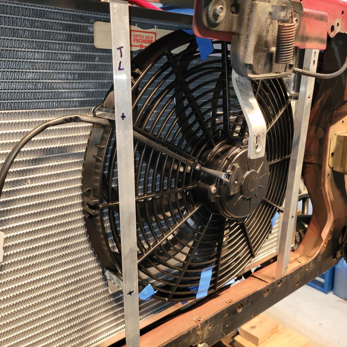


I drilled mounting holes in the frame being careful not to drill through the radiator (that would be a bad day).

That brings back a memory from about 1972ish – Patching radiators… I remember soldering a thin piece of copper patch on the top tank of my 1968 Mustang. Blow torch, steel wool, solder, flux in a little tin, and a little piece of copper strip about the size of a penny. We were on a ski trip up north. It was snowing. It took a couple of attempts to patch the radiator. But we got home from the trip. Yeah, we used to do stuff like that. Did not think twice about it. I think I went back later and brazed it to make it permanent. I think when I brazed it I got it too hot, melted a bigger hole, and had to start all over. One thing I absolutely remember though: We did not buy a new radiator. We fixed it. We fixed everything (eventually).

Here is the completed fan assembly. The fan is mounted on 2” long spacer couplings (hardware store) with the gasket barely touching the radiator. The spacers are mounted to the angles. Everything has some blue thread locker on it. There are some little nylon spacers where the angles mount to the frame. All the fasteners are ¼-20.
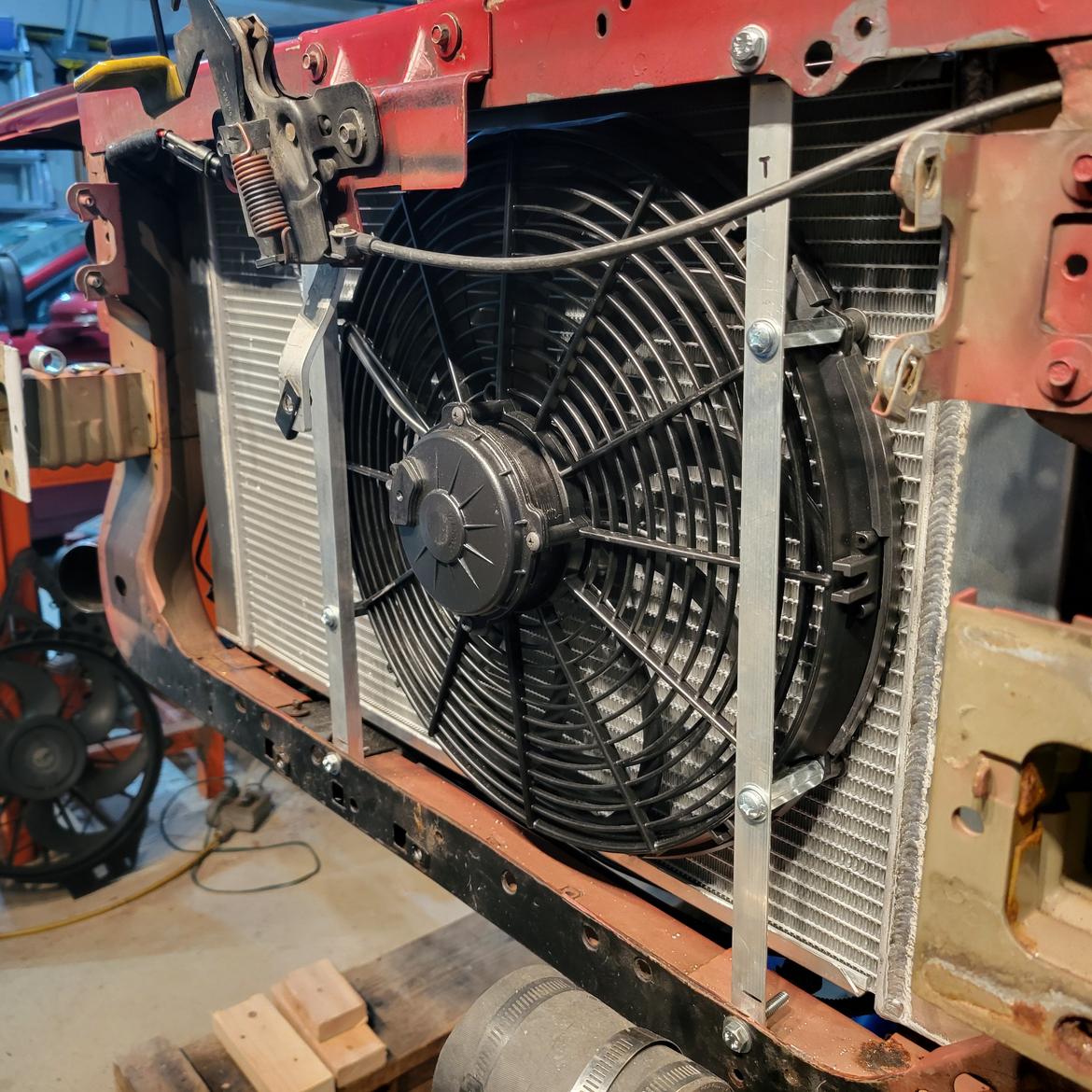
I noted in the last post the car was not wired for the two speed OEM fan even though the fan was two speed (as well as the programming).

For grins here is the OEM fan and plug:

And the OEM harness (note the missing connector in the center):

I still think it is comical that the car came with programming for a feature it did not have. And that I have had it for 22 years and never noted that the fan never went to high speed even on the hottest days.

I cut the plug that came on the Spal fan off and used one from Amazon. Apparently Spal and Summit carry matching plugs but I could not find them and did not want to pay shipping again anyway. Negative marketing. No sale.

Metal Fabrication

The OEM radiator was fairly well “boxed in” both with factory parts and some additional parts I made some time ago. Boxing in forces air coming in the front of the car through the radiator rather than spilling out around everywhere under the front cover. I used some flexible plastic storage dividers and gorilla tape to do this work. Gorilla tape is great stuff and you can fold it on itself to make flexible gaskets and seals for this purpose.

The OEM set up used a large electrical harness to keep air from running between the top of the radiator and the frame. It worked well and is an efficient design. It would work again for the new radiator but for two things:

Thing 1 – I needed something to mount the expansion tank on.

Thing 2 – I wanted to direct some cold air onto the engine air intake. The filter is right behind  the top of the radiator. It galls me a bit that I lost my cold air intake with the supercharger kit.

So, after some sitting and staring and messing around with cardboard I came up with a plan ( I would know later if it was a good plan or not).

The Plan:

  • Move the harness down in front of the radiator (above the fan). This will allow air to pass through over the radiator (about one inch clearance).
  • Fabricate a sheet metal cover over that one inch gap with a hole in it to allow a limited amount of cold air to blow on the air intake filter and provide a basis to mount the tank. I might later make a shroud for the filter to better contain the cold air.

My Neandertal metal working skills would be put to the test!

I started with making a template with some card stock. After a few false starts I was able to come up with a simple “bendiment” about 6 inches wide and 30 inches long.

I bought a piece of aluminum and while it was shipping made a crude brake on my workbench out of some angle iron. One angle was screwed to the bench top and the other screwed on top of that with the aluminum clamped in between. It is an old bench – Just drive screws into it.

The brake was a bit too crude. I had to score a groove on the underside of the bend to get a sharp edge. Most of the trimming was with a vibrating multi-tool. It was not perfect but serviceable.

The hole to direct some cold air into the intake was made with a hole saw and multi-tool.

To dress up this pig: Burnishing little spin circles in a pattern with the drill press. Little sander disks are from Harbor Freight. Easy to do and covers up a multitude of sins.

And the lipstick on the pig is to put 1/8” rubber edging (Bushwacker Fender Gimps 000040-01 from Summit) around all the cuts that are exposed (the multi-tool is not a precision instrument). You can see it around the cold air intake hole here:

Expansion Tank

The OEM radiator on the V6 model has the pressure cap mounted directly to it. This radiator is from a GT and does not have a cap so it needs an expansion tank and place to mount the cap. I wanted the expansion tank as high as possible. The OEM radiator cap was about 3 inches below the high point in the engine. This made filling and venting somewhat tedious. Raising the tank would help with this. But how high without getting into the hood?

With the car on the lift, I used a broom handle poking up through from the floor. I lowered the lift slowly until the handle was about to hit the closed (but unlatched) hood.

With the hood opened I marked the handle so I would know what height to set the tank.

With the tank height known I set about with new cardboard templates and made a support plate. The top of it is mounted on some 1 inch spacers from the radiator cover made above. The bottom is supported directly from the (now unused) OEM fan mount that came welded to the new radiator. I had to cut this down and then drill and re-tap it. A little trepidation clamping the new radiator to a vice and taking a hacksaw to it.

In for a penny?

And this would work well and look good. Hopefully I would not need to remember how to patch a radiator.

This fabrication was much smaller and easier.

The plate has a bend along the diagonal edge to add rigidity. This time I just used my wood vice and a ball pean hammer.
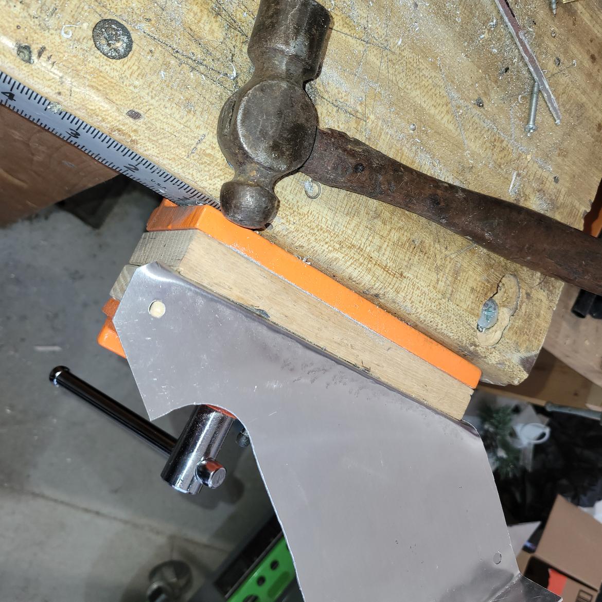
It is serviceable, does not block air flow, holds the tank properly and you really can’t see it anyway. In fact, once installed it almost disappears. I can’t even get a good photo of it.

Reassembling the front of the car required a few more "cut to fits" and "bumps to suit" to get everything to match up. The fiberglass assembly that mounts the headlights had to be trimmed in several places.

Nothing a little flat black paint won’t hide.

More Tank Madness

If your engine holds 2 gallons of water then the water expands about to about 2.2 gallons when heating from 60 degF to 204 degF. That is almost one quart. That is about 800 ml.

When shopping for aftermarket expansion tanks your choices appear to be limited to  800 ml, 1 liter, or 1.2 quarts (1.1 liter). After the first warm up I found the little tank would empty itself out the radiator cap to the floor. Fluid expansion on my engine is about 1.2 quarts. I must run with a non-pressurized overflow tank that siphons fluid back into the pressure tank through the cap on cool down. That means ALL of those overflow tanks on the market are too small unless you have a little four banger. All of them…

I ended up reusing  the overflow tank that Procharger provided with the super charger kit. I think it is not quite 2 quarts. Works fine. I think it is actually meant to be a vacuum tank. It is mounted between the fan and the bumper next to the intercooler.

Summary observations:

  • This was harder than expected. If I had bought only a two-pass radiator instead of a four I would still have had to move the fan. If I had bought a three-pass I would not have had to trim the air intake to the supercharger.
  • If I had bought a thin profile fan I probably would not have had to relocate everything in front of it. But those fans don’t move as much air so I might have needed two of them which would cost more. Would have been much easier though.
  • Even with the trials and tribulations above beveling the bottom of the bumper is providing much better air flow to the intercooler with little loss in strength.
  • The steel used in a modern bumper is incredible stuff.
  • The steel used in a Steeda Towel Bar Bumper is ordinary stuff. I look at it this way: I had my grandkids riding in this car at 90 MPH up the hill through the chicanes at Grattan Raceway last year. I want a #$%$ real bumper on the car please! One of them is now old enough to drive it at an event. Real bumper please!
  • My metal working skills are still laughable and hidden behind swirls and rubber gasketing.
  • Spal fans and Summit do a poor job at providing related part information for these fans. It creates frustration for customers and reduces their sales.
  • Mistress should stay pretty cool this summer and I can concentrate on driving between runs instead of how hot the engine is. This should make us slightly faster. A little. Perhaps.

V6Buicks
V6Buicks Reader
4/11/24 7:34 a.m.

I love your updates!  This car is turning out really cool.

Mustang50
Mustang50 Reader
4/11/24 12:23 p.m.

Kent should be writing DIY articles for GRM.

KentF
KentF Reader
8/15/24 8:28 p.m.

Taking Time and Making Time

I have written here that I did not think the boost gauge was particularly useful and did not need a prominent position on the instrument cluster. The clock (which was removed for the boost gauge) was sorely missed.

A few blown hose connections & broken serpentine belts later I have to modify that position. The boost gauge is a necessary trouble shooting device just like the air/fuel ratio gauges. When the engine is suddenly doing weird things these instruments are suddenly helpful to quickly troubleshoot what just went wrong (often before getting the car stopped).

If a blower hose blows off you can often hear it. But a partial blow off does not make the tell-tale booofing whooshing sound. Suddenly there is no power and you know what happened because partial throttle suddenly does not move the needle. And the A/F gauges are suddenly running rich.

It is pretty much the same with the serpentine belt but power steering is also gone (you notice that pretty quickly on an autocross course).

With the blown blower hose I can limp off course if it will still run and possibly get back to grid. With the broken belt there is no cooling pump. It will overheat in seconds.

So the boost gauge stays where I can easily see it when things suddenly go to hell. But I still miss the clock. At a Test & Tune we often sign up to work a one-hour shift. Lunch breaks are a fixed time (although they always seem to run long). The rain will get here about 2:00 p.m.  My phone sits much of the day mounted on the harness bar running Solo Storm. All day I am asking people what time it is.

In the before times I always wore a wrist watch. Always. When we started carrying cell phones I swore I would not be carrying two clocks. The phone is the new pocket watch.

The problem was where to put the clock. I was poking around this spring with some wiring and found a pretty darn good spot. The cigarette lighter socket!

There is just enough room back there to fit the back of the clock if you trim away some of the plastic bracketry.

After some careful measuring and marking I went for it and clamped up the plastic bezel with a block of wood as backing. The black mark on the wood in the lighter socket hole is where the drill bit is centered.

Then went after it with the hole saw carefully, slowly, working through the brittle plastic.

I had to trim off the threaded collar on the gauge to make it fit into the car.

Some black paint on the little bit of threads that show, and it looks like it was always there.

In other updates from the Great White North:

Mistress stays nice and cool now with the new radiator. I do not stay cool without AC in the car. Such is life. Drink plenty of fluids… Contemplating a small ice chest in the trunk with a pump circulating to the AC evaporator coil in the dashboard. It is not like I am taking long trips. Hmm…

I am now working only part time. Should finally retire this fall. My wife and I are enjoying making additional stops on autocross trips and being leisurely about it all. Here we are at a quilt shop on the way to an event. I often still have numbers on the car. You get a lot of funny looks from the quilters…

Having a great autocross season with two clubs and incredible venues.  Several more items to write up from this season. More to come…

Mustang50
Mustang50 Reader
8/16/24 12:34 p.m.

Good to hear from you again.  I'm living vicariously through you.  Would like to know how you are doing at the events this year.  Any videos?

I hope you both enjoy your retirements. 

My wife and I are both stuck in the house with covid.  I wouldn't wish this on my worst enemy.  We believe we caught it on a flight back from Aruba, great vacation lousy results.

KentF
KentF Reader
8/21/24 9:26 p.m.

In reply to Mustang50 :

Hi Mustang 50! I am doing OK at events. In first place in CAM-T with one club and second in the other. That is not a big deal though. Not many competitors and I have shown up to the most events. The old saying: "The world is ruled by those who show up." is very applicable here.

We were at an event in Oscoda Michigan last weekend. A video from that is below.  In July we were at another old AFB in the UP. A couple of videos from there are also below. One is best run of the day and the other has a tank slapper near the end. I whacked my head on the window (just like years ago where I got a concussion). No injury this time because there is roll bar padding there now.

These are full resolution so you may have to wait for them to buffer or just download them directly and play on your local computer. Best viewed on a big screen with the sound turned up.

https://applewd.com/Autocross/2024Videos/2024.08.16.19.54.25.852.KR-TankSlap.mp4

https://applewd.com/Autocross/2024Videos/2024.08.20.18.Oscoda-best.mp4

https://applewd.com/Autocross/2024Videos/2024.08.21.07-KR-Best.mp4

This weekend we are back in the UP again at a venue that has not been available for a few years. Contenental Tire Test Facility at Brimley Michigan. It is about 18 acres of asphalt. They don't have enough cones to use it all. Should be fun! Let meknow if you have trouble accessing these videos.

Mustang50
Mustang50 Reader
8/22/24 12:52 p.m.

Great videos!  It's good to see you enjoying the car after all the work you did.  Have a fun rest of the season.  I am so jealous.

KentF
KentF Reader
11/5/24 5:25 p.m.

End Of Season 2024

How am I doing:

About 85 or so more autocross runs this season with four clubs puts me at a grand total of 1100 or so. That is about 18 hours of seat time and ~825 miles over 14 years. No wonder it is hard to get really good at this sport!

No national level events this year. I wanted to go to the CAM National event in Peru, Indiana but it was moved to spring and I was not available. I missed a couple of local events due to health and one due to breakdown (I guess it is all breakdowns, either me or the car).

I retired this fall after 44 years of engineering helping people design all manner of manufacturing and chemical processing plants. Hundreds of projects creating plants employing thousands of people. Most of it on American soil. That’ll do. Sorry, we are closed now. I have some of my own projects to do.

My wife and I are working with some of the neighborhood kids introducing them to things like baking bread, canning, knitting, welding, household wiring, and the conservation of mass and energy.

How is Mistress doing:

Mistress had a very good season. One breakdown that I could not fix on the fly at an event was the bearings in the steering column. Suddenly the steering wheel was binding. We limped off course and I started taking things apart until I realized this was not a quick fix. Back onto the trailer for the five-hour drive home. Luckly, it happened near the end of the day. My granddaughter helped me remove the column, disassemble it, and replace the worn-out parts. I will write up the project this winter.

The steering column is about the only original hardware in the front of the car. 1100 runs x 40 turns per run is 44000 hard autocross turns plus 180 thousand miles before autocrossing.  I guess it was time.

There are a few other recurring problems:

The expensive SCT MAF does not have grooves in it to keep the air hoses from popping off with 12 psi blasting into the intake. Stupid design that could have been easily handled as the thing was manufactured. I will fix this and document it. I am sure it happens to other people.

I went through several serpentine belts over the summer. Only the Bando or Gates brands hold up for more than a few events. You might expect the expensive Gates Fleet belts (green) are good but they stretch too much and then burn when the tensioner runs out of travel. They are made for long term durability on trucks. They are not suited for these heavy loads and constant harsh RPM changes.

The belt is driving the twelve PSI blower, the power steering (a very heavy load with an over drive pulley on it), alternator, and water pump with constant RPM changes. It gets a serious workout.

So another project this winter is to make dead sure all the pulleys are precisely aligned. I think I have figured out a way to do it without getting crazy. I am also looking at a way to add a little more load from the tensioner. Not sure if that is a good idea or not yet…

But the big project is “Anti-Squat” (not Diddly-Squat).

Mistress has been talking to me in one-minute increments. Bitching at me actually. I put the throttle down coming out of a corner and she complains about traction. This car has a Detroit Tru-Trak so as long as both rear wheels are touching the ground we should be good but better hook up is needed requiring some changes to the rear geometry.

Unless the conditions and the course layout are perfect, I have been launching in second gear. Data logs show the additional acceleration from first gear is not worth the penalty of the time lost in the gear change unless temperatures and tires are perfect, and I have to lift for a turn anyway (they often put a sharp turn near the start to help equalize the course between the angle winder cars and the high HP cars).

So I have been doing a little light reading:

The book on top of the stack is the bible for Fox Body and SN95 cars. This winter the suspension is getting mapped and charted. instant centers and CG will be found and graphed, percent “anti-squat” calculated. Then the axle comes off and the welding begins.

Should be fun.

Mistress says she also needs more tire. That would certainly help in a class where cars routinely sport 12 inch wide wheels. We will see how the budgets go. But in preparation the rear axle needs reinforcement (it is only a 7.5").  I am not changing it to something more robust (and heavier) until I twist it apart. So along with changing the geometry we will be welding the axle stubs to the pumpkin and adding bracing. I might also add some camber.

LAST RUN

In the meantime, here is my last run of the season. An autocross at beautiful Grattan Raceway in Belding Michigan. Put on by SCCA WMR and Furrin Group. Not a normal autocross since it is making full use of this winding, two mile hilly road track.

Many of the turns are blind. If you get up enough steam and hit your marks you can catch air in one spot (I did not). On and off camber turns, Monza bowl, winding S’esses. The track is a blast. The autocross only makes use of part of the half mile straight since most of these cars do not have road track safety equipment and some of the drivers really don’t know what they are doing. 

A good way to end the season. I am just glad I ran last heat in the sunshine. In the first heat temperatures were in the low 40s (degF) and those 200 treadwear tires are like hockey pucks. It is like driving in the rain. It was still pretty cool in the afternoon, note the long sleeve shirt.

Last Run Grattan

Mustang50
Mustang50 Reader
11/6/24 1:01 p.m.

WOW!  What a great course, the best I have ever seen.   Looking forward to your updates.

Shavarsh
Shavarsh Dork
11/6/24 1:36 p.m.

Wow, what a course. You've done alot to the car since the last time I checked in. Beautiful work as always.

KentF
KentF Reader
11/20/24 1:25 p.m.

A Telltale Tale

In designing various process systems, it is sometimes a good idea to make an operational problem obvious. That is really what the idiot lights on your dashboard are doing. But sometimes a potential problem does not warrant an actual instrument circuit. Sometimes you can call attention without spending a dime and/or sooner than the instruments would. Sometimes you need something that still works when all else fails.

Late in the season while waiting my turn in grid during a downpour Mistress threw a Check Engine Light. A scan of the instruments indicated she was hot. Very hot. This was several events after the new radiator and fan were installed.

Standing in the rain I realized that she had emptied most of the coolant out of the radiator overflow. The new fan was not running and the engine was about to run dry.

I did not really have time to figure out what was wrong but decided to just hot wire the thing. A quick run to a nearby parts store for a 50 amp inline fuse, some 12 gauge wire, and coolant and I was back in business. I even managed to get a couple of runs in that morning. I left it hot wired all weekend. If the car was on the fan was running. Worked fine.

However, if it had not been raining this would probably have been noticed long before the car actually tripped the light. There was no steam plume as the hot coolant was immediately quenched as it fell 8 inches into the rainwater under the car. People all around and no one saw it happening. All that coolant went down the drain in the rainstorm. Not good. Not acceptable.

Each spring we watch one or two Nascar races before we decide it is not worth sitting through all the commercials. Same with IMSA. But I have noted that Nascars vent their coolant out of the hood on the right side. This is an excellent and foolproof “telltale” that something has gone wrong. Always works. Can’t be broken. However, a Nascar is out on an enormous track and anyone who might get near it is wearing protective gear. Not a good idea in a busy autocross grid. But perhaps I could use a variation on that theme…

The overflow bottle is down low behind the bumper. I added a brass tee to the vent line.

The upper leg of the line (for vapor) ends at a fitting made from a plastic automotive push pin with the center core removed.


The fitting holds the vapor discharge up in the grill at the front of the car. It is almost invisible.

The normal flow for most of the liquid should still be down under the front of the car. But some vapor should find its way up to the grill where it would be visible and dope slap obvious (even in the rain).

It might spit a little if things get really bad. But if things get really bad no one will get near the car anyway. It has not been tested. Hopefully it never will be.

1 ... 13 14 15 16

You'll need to log in to post.

Our Preferred Partners
E4qEHHGI3oEJlc5tOL35NvLKksV79vl0P9XQpCPbYc03NsQ8CJFnZ7SWzJjWr8aO