1 2
Cyclone03
Cyclone03 New Reader
9/8/24 10:55 p.m.

Thanks for your inside Pete.

Kinda too late though.

My lower links are 21.75 upper is 17.75.

rear axle is a Quick Performance fabricated housing with 1/4" wall tubes as well as 1/4" center.

The upper mount is 1/4" with for and aft gussets as well as side to side.

The upper forward mount is actually the same mount as the axle one,(sourced from Ruff Stuff off road as a pan hard bar mount,1/4 thick and 5 adjustment holes.

I leveled the lower arms at ride height then using the hole closest to the housing,upper, I set the upper forward mount UPPER hole 1" lower. That upper hole is inside the car,due to the angle of the floor pan I lost the second hole down I still have 3 lower.

All together I moved the upper to all extremes and cycled the axle to check clearances my only interference is laterally on the upper in extreme roll to the floor in the trunk, I guess 1" on either side isn't enough,no biggie at this point. I'll weld a nice cover in to fill what ever hole.

I repurposed a Fays 2 Watts link using duel clamp on axle mounts,It was for a 71 Mustang so I removed the frame brackets,lowered the frame about 2" and hot glued it all back together.

Moving it by had its all smooth and I think looks really cool.

So it's in place just needs to be made a bit more presentable ,and then engine/trans/cross members / shock towers notched plus everything else......

picture dump next.....


I was going to load some pictures but the small medium and large options are gone ,what height /width should I use to get the old "small" pictures.

Cyclone03
Cyclone03 New Reader
9/8/24 11:09 p.m.

Asphalt_Gundam
Asphalt_Gundam HalfDork
9/9/24 8:50 a.m.

Add some gusset bars to the upper chassis side link. Front the front side down to the frame/or lower mount. As discussed before, a lot of force goes through that upper link. You don't want it to move/rip the floor out

Cyclone03
Cyclone03 New Reader
9/9/24 8:15 p.m.

Here is the front upper as installed.

That is a 1 1/2" DOM with 1/4" wall cross member welded to the upper mount,do you think that will twist?

Asphalt_Gundam
Asphalt_Gundam HalfDork
9/11/24 7:23 a.m.

I'm using the factory 4 link cross member on mine and was told by the only other person I know who 3 linked a G body that it NEEDS reinforcement.

Think about it this way. You have a long tube and you're applying the bending force in/near the middle...its going to move.

I went with a tube that ties into the lower mount and welded to the backside of the cross member at the upper. I believe the other guy went with triangle gussets over the axle from the frame to cross member.

I made some drag passes last weekend with my car and it was hooking up pretty good. But I was a little nervous considering the launch forces of a 3640 lbs car are largely going through that one upper link

Cyclone03
Cyclone03 New Reader
9/11/24 12:22 p.m.

My crossmembers started as a RideTech triangulated 4 link kit frame. 1 1/2" front and same size rear that the coil overs mount to tied together with 1 1/4" 1/4" wall tubing.

I understand that my front mount is effectively a tower and lever. Upper hole 3" from center of crossmember lower near 5".

The smart and maybe easier thing is to have a roll bar installed with the down bars running to the top of the coil over mounts,a harness bar at correct height then kickers from that point to the top of the forward 3 link mount,nice big triangle,and of course kickers to the subframe connectors.

The problem is backseat is gone,no little humans. Those little humans are the little humans of my little humans all grown up.

So I'm trying to avoid that.

My first thought is tie the upper to the rear cross member with a single curved bar.

2nd 2 bars again to rear crossmember near the upper coil over mounts ,yes a triangle.

3rd, as #2 but add a single bar forward at a low angle to the floor with a sandwich mount .

4rth, as #2 but two bars forward with the inboard running into the radius of the driveshaft tunnel ,outboard near the rocker,triangles forward and back.

Seat bottom a bit lumpy but a bit safer than being hit in the head with a 1 3/4" pipe.

As a point of reference Street or Track has a 3 link kit for Mustangs, he uses a sandwich mount for the upper that contours the drive shaft tunnel and bolts in. Now it is a single mount point with no adjustment and appears the loads travel for and aft along the driveshaft tunnel ,so minimal rotating load.


Now if I pretend I know math and assume 400lbft torque,2.66 first gear and 4.00:1 rear gear I have 4200 lbft available acting through an axle lever up to 10" from axle C/L so are we now close to 8000lbft (a 12 arm would double the available torque ?) at the end of the axle arm? Now that 8000 gets to push on another lever only say 4" tall so 10,000 lbs of twist on my front cross member...

If we assume 2:1 safety factor I need to control 20,000 lbs of shearing force across 4 mount points with my low angle arms or high angle roll cage....

so I like sweat ice tea with BBQ brisket.


Will 4 1" DOM tubes with .120 wall carry my WAG 20,000 lbs? Or 1 1/4" .120? @ my low angle under seat mounts?

Asphalt_Gundam
Asphalt_Gundam HalfDork
9/11/24 3:38 p.m.

Mine is 1-1/2" .120 wall DOM tube with around a 30-40 degree bend. I don't think it needs to be super crazy reinforced. But would also tie it in on mine to cage if cutting the rear floor section completely out.

Option #2 looks like it would fit well for you

Pete. (l33t FS)
Pete. (l33t FS) GRM+ Memberand MegaDork
9/11/24 7:09 p.m.

I had, say, 190ft-lb acting through a 3.63 first gear and a 5.43 final drive, for about 3700 ft-lb at the axle.  I always made my brackets out of 1/8" mild steel from the hardware store and used 3/4" thread Allstar swedge tubes for the tubes.  Or 3/4" black pipe from Home Depot, butt welded to old bushings.


You have more umph but also not so much that it would be like an order of magnitude more.  Your current state of overkill should be just fine.

Cyclone03
Cyclone03 New Reader
9/24/24 12:35 a.m.

We'll update time.

Normal disclaimer: ignore the rust holes, repairs are on the way.

Here is the new triangle upper mount support.

The two arms are welded to plates welded to the coil over cross member as well as the upper forward mount.

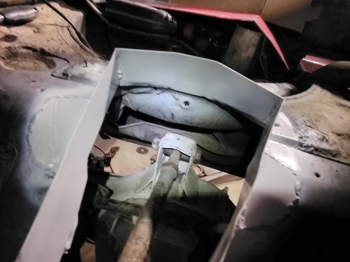
Also the cover for the axle mount,amazing how much that mount rolls side to side.

Cyclone03
Cyclone03 New Reader
11/3/24 12:10 p.m.

Floors all welded up,braces in place and everything painted black so nothing stands out in pictures but it's all in.

Everything cycles very nicely ,centers stay in place,pinion angle stays within 2 degrees ,more like 1.6,over full wheel travel from extension to compression.

Hopefully the rest of the project continues and I can drive it by next years snow melt. I hate weather.

Pete. (l33t FS)
Pete. (l33t FS) GRM+ Memberand MegaDork
11/3/24 12:13 p.m.
Cyclone03 said:

We'll update time.

Normal disclaimer: ignore the rust holes, repairs are on the way.

Here is the new triangle upper mount support.

The two arms are welded to plates welded to the coil over cross member as well as the upper forward mount.

Also the cover for the axle mount,amazing how much that mount rolls side to side.

I think the hole in the floor for my 3 link is 10" wide at the back because of articulation.


Part of that is because the 3rd link has to clear the Watts link underneath it... that had to be raised a bit to clear the rearend because a 9" is a lot bigger than a Mazda 7", even after deeply shaving the top of the pumpkin.


The nice thing is that I can adjust pinion angle from inside the car smiley

1 2

You'll need to log in to post.

Our Preferred Partners
4PyGFeFfOHQ1lWGpTvm1ECckD7KUT6NlVzj2WyhoKGmrvX7EnAxJUOYIXeLK9i7N