I had an 18 psi cap on the rad and a 16 psi cap on the expansion tank and had no trouble with it. Make sure you have a steam hose going from the highest point of the engine to the expansion tank. Air (steam) will go through that hose into the expansion tank and push the coolant in your expansion tank into the cooling system. This bleeds the air out of the cooling system.
This is exactly why i spend way too much time in front of the 'puter. I buzz sawed thru this ...did I miss the the trans mashup? Your fab skills are hall of fame here (is there a GRM hall of fame)......Binkyish I must say. Big thanks for the journey, my MGB/GT-Typhoon awaits me....
In reply to 759NRNG :
Wow - thanks for the compliment 759. I am not in the same league as the Binky guys. I wish I would have watched their early episodes prior to my engine bay. Negative jig thingys would have helped me out. I have used several "normal" jig things on my build. Their latest episode (16?) with the illustration of how long it takes to make a bracket is spot on. Projects like what I am doing are essentially death by a 100 brackets.
Not much mashup with the trans. The 96 Crammit V6 that is donating its L36 motor and brain came with the T5 so other than a disk pack replace and flywheel resurface I'll be good to go until the time comes to adapt the L67. Then there will be some mashupage.
And BTW thanks to whomever changed my thread title!!! 

Sparkydog said:
OK hive - time for some help with radiator plumbing. I want to "bury" the radiator cap under the nose skin of the 944. So normally I will not be able to access that cap. Instead I will use the expansion tank cap for normal servicing. If I have to fill the coolant from scratch I will break open the return hose at the top of the block. Trapped air will be bled off with the screw.
So my basic question is "will making the normal pressurized radiator cap inaccessible bite me in the ass?"
This is basically how the 944 was already engineered, only they didn't put a cap on the radiator, but I'm sure their engineering is suspect since it isn't a GM or Ford :/ (Sorry, I respect your fab skills and work, but I don't understand the comments about the suspect VAG engineering, especially when some of the better parts of it have been replaced with parts that aren't nearly as good.)
A radiator shop can close off the radiator cap on aluminum and brass radiators or you can use a blanking radiator cap, or make one by soldering one closed, but the seal can still eventually fail and leak.
If the hose is run as pictured, I think you still could get air in the system. The hose should run uphill to the expansion tank.
I know it's just a quick drawing to show routing not position but make sure you allow air to rise into the tank
Sparkydog said: So my basic question is "will making the normal pressurized radiator cap inaccessible bite me in the ass?"
Short answer, yes.
FWIW, I have an 06 Xterra that is almost literally designed this exact way minus accessibility issues. They actually use a special cap on the radiator that only the upper seal, and no recirculating garbage. Only problem is it's the little Jap-car rad cap, so probably only helpful in theory. Unless you can get a custom cap or modify one.
I'm anxious to see how you progress with this one. I have a weakness for overly complicated builds with absurd amounts of fabrication.

Stefan - thanks for the advice and no worries about any difference in opinions! I don't mind - you are welcome to challenge my thinking at any time!
jfryjfry & Crackers - thanks also for the feedback!
Well I'm a guy who seems to do well with punch lists and deadlines. So my next milestone is to get the starter to bump the motor on or before mid February 2018. I realize this doesn't sound very exciting but hey, it's making progress! So in order to make that deadline I have to accomplish this:
- Use a wire to mockup the routing for my clutch hose and get it made. Also mockup my clutch remote bleed line and fittings.
- Pull the motor out again and install a new clutch slave and throwout bearing. Install hoses too. Also repair some stripped threads on one of the motor mount holes.
- Seam seal trans tunnel area.
- Return motor and trans to their happy place inside the 944. Install trans bracket 3.0.
- Finish batt cable lugs & install grommets in various pass-thru holes. Verify that battery is charged.
- Find my remote start switch and install.
- Test for presence of starting. Verify that smoke remains inside.

And then the next milestone will be mid-Summer engine running:
- Install engine wire harness, ECU & a temporary power feed with switch. (I don't want to mess with using the 944 ignition switch just yet.)
- Seal fuel tank. Install fuel lines & Evap. Leak check in situ but before adding gas.
- Complete fuel pump circuit, verify fuel pump runs. Add gas, final leak check including fuel rails.
- Oil in motor. Maybe oil in trans - maybe not yet. (Don't need car to move yet & may pull motor again.)
- Decide how to bypass A/C compressor (for now). Either block off ports on the compressor or fab a dummy idler pulley so that I can use stock serp belt.
- Get PS pump and steering rack to talk with one another. Either adapt GM pump to Ford operating pressure or adapt Ford pump to GM pulley. Since this would involve fabbery and possible bracket making I will probably go this route. Install serp belt.
- Install coolant expansion tank. (Brackets!)
- Engine bay fuse block and/or under dash fuse block. (Brackets!)
- 1st attempt at dealing with VATS/Passkey shenanigans (may involve finding my Camaro BCU = more brackets!).
- Verify oil pressure. Verify fuel pressure.
Troubleshoot until motor starts. Troubleshoot until motor starts and stays running.
- Connect radiator & related items. Furnish with coolant. Get cooling fan/fans operational.
Troubleshoot until motor runs continuously.
(Exhaust intentionally left off the list but will need to be inserted into list at some point. Upside-down fabrication is not my favorite thing.)
On my car the separate tank has 2 hoses, the small vent /air bleed that you show, is connected to the top of the tank. There is a second hose at the bottom of the tank that is T connected to one of the radiator hoses. That way the tank will fill the system and air will bleed off the top of the radiator and vent into the top of the tank. Mine doesn't have a cap on the radiator, so if your cap doesn't vent then the vent hose won't work. With the bleed screw you should be able to vent the air, but should have a feed hose from the tank to the system.
Might also want a vent from the top of the system to allow air or steam into the tank, since the radiator vent hose won't vent until the cap lifts.
I do admire your fabricating skills, and willing to cut things up try things out.
I'd kill (okay maim) to have a buddy doing a project like this.
I'd bring the beer (mix the margaritas) make parts runs, do the Googling, whatever. The experience to be gleaned looking over your shoulder would be invaluable.
Way to enjoy the hobby and life, good for you!
In reply to TED_fiestaHP :
+1 vote for the two-hose method. RWD Volvos have a small hose from the top of the radiator to the coolant bottle, then a larger (5/8" ish) from the bottom of the coolant bottle to the side of the radiator, maybe 1/3 of the way up. There's only a single cap, on the bottle, and the fill process is super easy. Dump in coolant until it's full. Start the car, get it up to temp. Top it off. That's it!
I figured out my issues trying to get the starter to bump. Nothing that cleaning all the grounds, actually tightening the starter mount bolts and getting a healthy battery couldn't fix!  heh.
heh.
In reply to Sparkydog :
Funny how that works sometimes. ;-)
Between scampering around dodging fires at home and work - I managed to get some more fabbery going. I mimicked the 944 shift boot ring but made a bigger one that would allow the shifter for the T5 to come out the top.

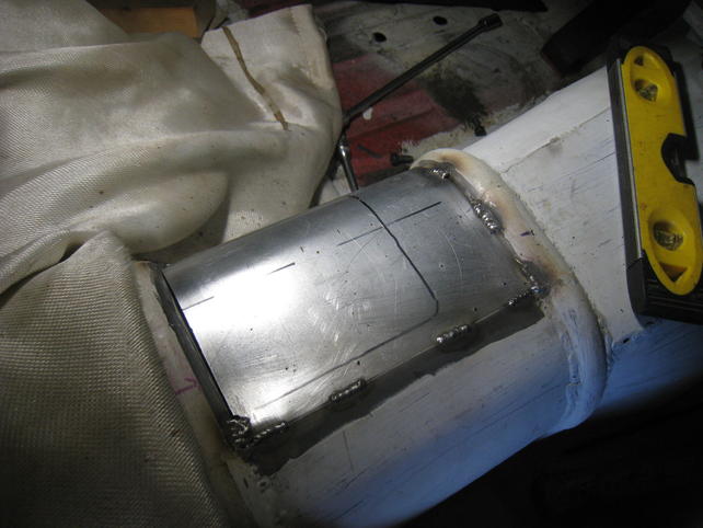

I need to flip the car around in the garage before I can finish off the far side of that ring.
Next I created some clearance pockets for the new radiator's cap and return hose.
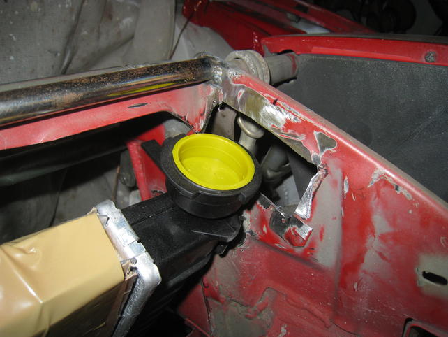


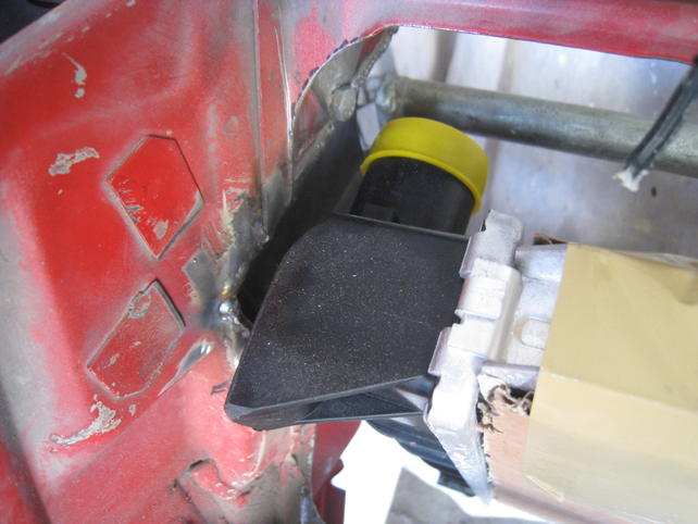
Next up will be the mounting brackets for the radiator itself.
Whenever I do get the L36 motor running I will probably have it in the car for about a year before attempting the swap to the L67. And during that year of L36 I will also NOT be trying to hook up my A/C system.
So the next thing that I would like hivehelp on is how to bypass the A/C compressor. Here are some initial ideas:
- Buy and install an official AC compressor bypass pulley (& bracket) for about $30-50.
- Assemble the AC compressor on the motor, leave the hoses/port-block off of it and just let it sit there with the ports open to the wind/dirt. Replace sacrificial compressor a year later when I want one that works.
- Assemble the AC compressor on the motor and cut the in/out pipes off and crimp them closed in a lazy attempt to protect the compressor for the year or so it rides around in the engine bay without proper connections.
- Cut in/out pipes as per #3 but instead of crimping them off - just splice them together in a little DIY loopy.
Advice?
Finally clicked this build and I'm sure glad I did! I have never heard of an engine bay swap. That is a clever solution and looks like a ton of work, but it turned out great. Nice work, looking forward to more.
"Ask not how you can fit the motor to the car... but how the car can fit the motor!!!"
Sacrificial compressor seems to be the least expensive option for the moment, since you already have one. It may also be possible to run without a pulley in its place. At least on older Buick V6s (Series I and 3300s), you could just run a shorter belt and take the AC out of the equation entirely. I may be wrong, since you have a rear wheel drive Series II, and running a bypass/shorter belt may end up spinning the water pump backwards, and that is not ideal.
I initially thought you were going to run an LT1 when you mentioned '96 Camaro, but I never dreamed of a Buick V6 until I saw the coil packs. I like the cut of your jib, son. I think you'll be pleased with the torque of the supercharged version, and admire your plan of stepping up to the higher power version at a later date. Responsible.
Thanks for the suggestions Left V!
Continuing on with my theme of "Death by a 100 Brackets" - I give you my next bracket. It's a big 'un and causes the assimilation of the Ford radiator into the prow of the 944.
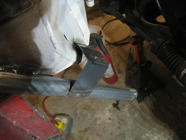
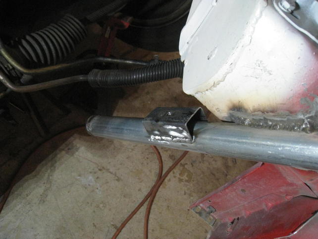
First was the fab of what would be the side pipes/horns to which the bottom core support would bolt to. Also shown in these pics are the start of the ends of the core support - with the little cutouts for the rubber donuts that the radiator fits into.
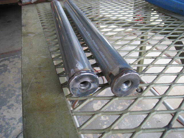
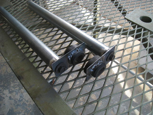
And then the bottom bracket itself. Replete with some hems and a nifty Z section.


All welded up! (Well OK - I left out a couple of steps where I had to do some stuff over.)
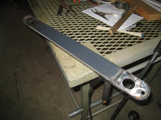
And then on to mocking it all up with the radiator, then scarfing out the necessary amount off the tubes - and then tacking, then welding the side braces into the car.


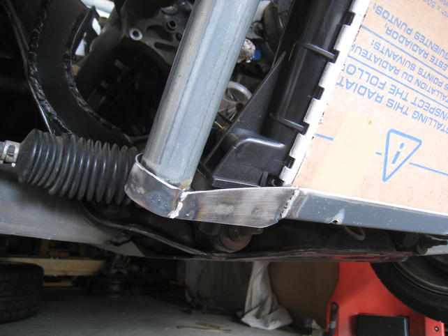
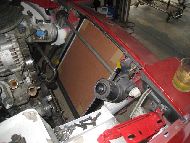
Donor metal: Side pipes courtesy of the chain link fence section of Home Depot. Bottom bracket metal came off a "kit" that comes with Brother R450 CNC mills. We never use the kit at work but the sheet metal is awesome so some of it usually follows me home.
I don't know how long this link will stay up but I thought some of you might enjoy reading/watching the vid:
Paper airplane linky.
Aaannnnnd 3 more brackets.
All involving the mounting of the Mustang fan assembly to the 944.

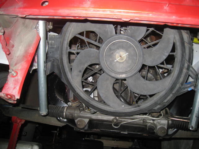
Top bracket that "cups" the fan shroud.

Righty bracket
Lefty bracket
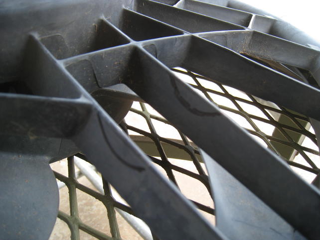
The fan is from the donor Mustang. It's now oriented upside down from the Mustang. I also had to cut on it twice.
The arm/brace structure had to shrink down.
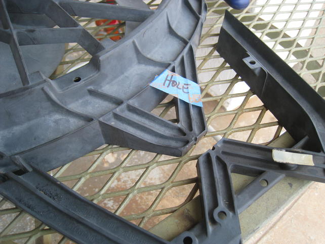
And I had to clearance two ribs where the 944 headlight popup shaft hootywacker crosses over them. You can see my marks on the fins in this picture.
