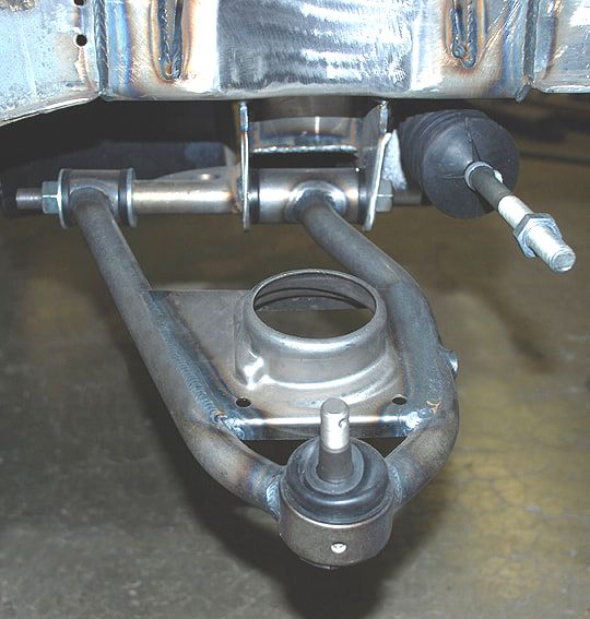
In an effort to delay major modification to the car I decided to build a jig to locate the miata lower front control arm chassis mounting points. This allows me to easily see if it will be easier to install the whole subframe, or build control arm mounts on the existing structures.
First some precision bushing locaters:

Next set them all at 90 degrees adjusted all the way in on the alignment bolts:

Then build a square frame, measure a few key spots and weld it up:

That steering wheel is awesome, perfectly matches the attitude of this car
And, amazing fab work as always


Thanks maschinenbau,
Unfortunately the jig shows some glaring interference with the pinto frame rails at the rear lower control arm bushing. While it is possible to remove that section of the frame rail and reroute to fit the suspension I am starting to question the need to significantly alter the front end. So I'd like to ask for some opinions from the crowd here. My options as I see them are as follows: significantly alter the front structure of the car to fit the miata front suspension, refresh the stock 1973 pinto with expensive stock parts, "improve" the stock suspension with fabricated delrin bushings for the control arms, or design/fabricate new control arms and mounts that fit the available space on the chassis. Here are the pros/cons I see with each direction:
Miata suspension
- significant fabrication needed (time off the road)
- matches the rear suspension geometry (as designed mazda handling)
- I have a miata front suspension
- matches the 4x100 stud pattern for matching wheels/only one spare tire
Stock parts refresh
- parts are available and will result in the least down time
- current handling is enjoyable
- difficult to adjust alignment settings
- some parts such as control arm bushings and ball joints are very expensive
- limited room for future development
Fabricate delrin bushings for stock suspension
- reduces cost significantly over stock rubber
- doesn't require long downtime or significant fabrication on the chassis
- limited room for future development
- ball joints are still quite expensive
Design/fabricate front suspension
- fun project
- will take significant time and effort
- will need to take more time to learn/measure/decide on proper geometry choices
- ability to use common parts for cost/availability advantage
- common parts use will allow for future upgrades
- ability to use 4x100 miata spindle to match lug patterns
I'd like to hear what opinions are here on the board to inform my decisions a bit. Input?
In reply to Shavarsh :
The Pinto front end is pretty good to start. I would consider making some eccentric bushings to give camber adjustment, or possibly making new upper control arms for the same reason, and keeping the rubber because street car. Keep the stock lower control arm because it is disposable if you have a suspension bending incident. Stronger arms just damage the chassis instead. Check the bump steer and adjust it by bending the steering arms or similar if needed. The geometry is not that different than the Miata.
At some point good enough is good enough.
Delrin, fresh joints, send it
Are there any simple upgrades available in the universal circle track catalog for the early Pinto front suspension? Might be a work around for the expensive ball joints?
Gumby is on point about the circle track stuff. There used to be a crap ton of Pintos racing short track. Maybe something is still out there.
Thanks all for the responses!
One of my issues with the stock suspension is the strut rod setup. It seems to me the lower control arm will bind if I replace the lower control arm bushing with anything firmer than rubber. In concept the caster will also change with bump. Converting to a true lower A arm makes sense to me but I have a limited amount of space to separate the 2 bushings on the crossmember (6 1/2" outside to outside). If I can fit a bushing in the location where the strut rod bushing is that is on axis with the lower control arm that would be ideal. What are everyone's thoughts/experiences with strut rod suspension? Is it an inherently poor system, or is it worth working with? Currently the bushings are definitely trashed and you can feel the car go toe out under braking.

Edit: Here is an example of a control arm that has the bushings close together (credit full tilt street rods):
Keep the rubber, just refresh it when required. If it was a dedicated track car I could be persuaded into spherical bearings, but both their loud noise, and their life span is too short for a street car, and polyurethane is an awkward compromise in this location. Poly on the strut maybe OK, but keep it rubber at the inner end for sure, and that position's life may then be compromised.
We do a Johnny Joint on the Mopar strut rods. When I did the AMC I use the pair of heim joints and made my own adjustable strut rod that was much Freer movement than the original that was similar to yours. I also can we trust the veterinarian Center pivot from a rubber bushing to a heim joint so I could then free up movement there as well as you suggested for camber and caster
I decided to keep the scope limited to maximize driving time. So a full replacement set of reproduction 73 pinto front end bushings are on their way. Hopefully I have success removing the old bushings with my new to me 12 ton harbor freight press. Thanks all for chiming in. The path I see going forward is to get the front end bushings all refreshed, then once driving again I can order the front shocks, and down the road I'll swap in ball joints and spindles from the miata. The spindles are remarkably similar and I should be able to preserve the geometry with different height ball joints.
It looks like there will be some rust repair in my future. Here is what the drivers side strut rod mount looks like:

and here is the passenger:


This is undoubtedly where the steering wheel shake and toe out under braking was from. The part of the mount I'll call the "outer race" is absent, part of it came out with the bushing, but most of it must have left as dust. Before removing the passenger side strut rod it could be moved almost a quarter inch in and out by hand. My plan is to clean everything up and determine if the ugliest parts can be left alone and new metal can be added to the "good" side.
Then, installation. The welding was challenging but overall turned out better than expected. I only got pictures of the passenger side, however the drivers side went a bit easier.
Out board:

In board:


After that they were slathered in etch primer and paint. I figured it was smooth sailing from there... but I didn't have the upper control arms off yet.
Many thanks to Engine Swap Depot for the article!
https://engineswapdepot.com/?p=83135
So, the upper control arms. The passenger side came off nicely. However getting the drivers side off was a bit more involved. When I put the ratchet on one of the cross bolts I very easily removed this:

Well, at least the top part came out easily. Someone must have snapped this bolt a looong time ago and just placed the head back into the hole to avoid getting in trouble. It rusted back into place over the years and I am just happy that it didn't let loose while I have been driving the car. Removing the cross shaft from the lower half of the bolt took lots of heat, penetrating oil, and time. Afterwards a spare nut and breaker bar took car of freeing the sliding nut (which we need to reuse).

All of the sliding nuts were in less than optimal condition so the threads were chased and the mating surfaces cleaned and painted to hopefully slow the corrosion in the future.

One of the reasons I wanted to get rid of the early pinto suspension in the front was parts availability. So I was pleasantly surprised to find multiple options for upper control arm bushings available from the local store. After bushing removal I tried to press in the moog bushings I chose.

I didn't take any pictures but I will summarize the bushing install. One set of bushings slid nicely onto the cross shaft, one set needed to be pressed on. Then the bushings started to swell and deform before pressing into the arms. After a bit of measurement the bushings had a 1.40" OD and the ID of the arms are 1.25". That's pretty far off, so I called moog and they agreed I must have gotten some miss boxed units as the OD they expected was 1.26". Long story short 7 sets of bushings from the parts store later have all come in at 1.40" OD. Now that I know I can reliably get 1.40" bushings I set about modifying the control arms to accept them.
1 3/8" is the highest step on my step drills. It also is 1.375 which after drilling by hand will be a bit larger than that. This should be an acceptable interference fit for the 1.40" bushings.

This removes most of the meat where the bushings press into, however due to the support from the cross shaft I don't believe it will be an issue. If the bushings don't seem stable in the arms I can throw a couple tacks on them. Hopefully once this is sorted out I can reassemble the front end.
Well, after drilling out the arms and pressing in the new bushings another issue appeared:

These bushings are also shorter than the correct bushings. This confirms that the bushings are completely incorrect for an early pinto, very likely they are correct for a late pinto/mustang ii. To correct the problem press the bushings back out and fire up the lathe:


Perfect, problem solved. However a new problem became apparent after pushing the bushings in/out a couple times:

Drilling had removed too much material from the bore that the bushings press into. So the return on the bore was removed and the bushings heavily tacked in place:


Reassembled with fresh hardware:

Then finally back on the road:

I am not satisfied with the current quality of the upper arms. This setup will certainly work for now but I expect to build a set of control arms that are less cobbled together in the future. I am however, super happy to have the car up and driving again.
Well, with the first autocross for this car since the IRS/Frame install we need to perform an alignment. But first, we need to set ride height. In an effort to be more scientific than in the past I decided to corner weigh the car and attempt to balance it. Here is my scale setup:

And here is my stunt double in the drivers seat (~145 lb):

Here are the results with 1/4 tank of gas and rear shock compression set to zero:
Front
Driver Passenger
784lb 718lb
610lb 656lb
Total: 2768lb
Front: 54.3%
Rear: 45.7%
These are actually good results. They agree with the 2620lb measurement I had from the truck scale with the additional ~145 pounds I put in the drivers seat. The front to rear bias is better than I had been estimating. To even out the weights I need to remove weight from the front drivers wheel. This is good because I know this spring is a bit too long and that corner of the car is high. Also, a bit more gas in the tank will mostly add weight to the drivers rear, another positive. Hopefully I can make these changes this weekend and remeasure.
Stunt double's got a nice shaft.
or two?!?!
My measurement method has proven to be quite variable. This hasn't stopped the progress though. First, trim the drivers front spring .25" in height to 8.5", fill the fuel cell to 3/4 full on the gauge, and remove the front bumper over-riders. Then remeasure. Next, add .25" aluminum shim to the passengers front spring to land at a total spring height of 8.5". With a helper in the drivers seat here is where we landed:
Front
Driver Passenger
764lb 731lb
674lb 634lb
Total: 2802lb
Front: 53.4%
Rear: 46.6%
Left: 51.3%
Right: 48.7%
Cross: 50.1%
After these measurements I added 1/8 turn to the passenger rear corner (lowest height) and called it good. I am not going to get any better than the current cross weight measurement without more precise measurement techniques.

Now that the corner weights are acceptable it is time to start the alignment.
Unrelated: the passenger rear viking shock has developed a loud squeal when rebounding. The noise is less when there is less rebound valving dialed in. Are there any tricks to stopping this squeal? I'll be contacting viking to see what they say, its pretty loud in the cabin.
Shavarsh,
I'm immersed in a 1974 Pinto wagon V-8 project. I'm interested in
which water pump you used and which pulleys.
Thank you !
Wishfulthinker
In reply to wishfulthinker :
Hey Wishfulthinker, sounds like a cool project! I'd love to see some pictures if you want to start a build thread here. As for the water pump and pulleys, the pump is a standard rotation standard length pump (nothing fancy). The pulleys are a cheap ebay set of aluminum v belt pulleys for 302/289. Let me know if you need more information but again, nothing fancy.
Shavarsh said:
One of the reasons I wanted to get rid of the early pinto suspension in the front was parts availability. So I was pleasantly surprised to find multiple options for upper control arm bushings available from the local store. After bushing removal I tried to press in the moog bushings I chose.
I would be surprised if suspension parts availability was a problem, considering that Pinto/Mustang II is the basis for so many hot rod and drag race front suspensions.
So to finish setting up for autocross we needed an alignment.
While visiting home recently my father gave me these tools:

These are the proper tools used to adjust the front suspension on a pinto/mustang ii. He has had them for years and its pretty crazy that I happen to be modifying a 73 pinto and he happens to already have the specialty alignment tools. Thanks Dad!
These tools make adjusting the front suspension as easy/easier than using eccentrics. Here they are installed:


Here is how I completed the measurements, caster/camber:

Keeping track of each change:

Measuring toe:

In the end here are the specs we ended up with:
Front
Driver: Passenger:
Camber: -1.2 -1.25
Caster: 4.36 4.15
Toe: 1/16 in total
Rear
Camber: -1.25 -1.3
Toe: 3/32 in total
All toe measurements taken at the edge of the rim on 15" rims.
For the autocross I ran a full tank of gas and 45psi in the tires (cold).


