1 ... 6 7 8 9
WondrousBread
WondrousBread Reader
3/1/24 10:50 p.m.

I thought of a few mounting locations that might be possible candidates for the hall sensor. In counter-clockwise order

- Current location, installed on the mount for the air pump adjuster (9:00)
- Down where the OMP lives below the air pump with a bracket to pick up the OMP bolts (7:30)
- Right side where accessory bracket mounts (3:00)
- Picking up on stock CAS mount (1:30)

9:00 is a no-go because there's no good way to keep it there. The air pump adjuster is one thing, but the belt will want to run right through the back of the sensor which means changing the air pump mount as well.
7:30 would work, except that the OMP lives there and it would be extremely difficult to keep it while also mounting the hall sensor on it.
1:30 would put the sensor directly in the place the AC belt runs. All that does is kick the can down the road until I want to put the AC back.

So that left me with 3:00, which is exactly where FFE locates their sensor. It's obvious why they chose that location, but what wasn't obvious to me was why they didn't offer a kit that was compatible with the stock accessory bracket. I figured that all that was required was a simple bracket for the sensor and some spacers for the accessory bracket.

Here's what I came up with:


Test bracket printed and installed:


As you can see based on the 1/4" gap, I will need some spacers for the remaining three fasteners on the accessory bracket.

From above:


Sensor gap is a bit too wide, but it's close


Here's one of two probable reasons that FFE doesn't offer a kit that works with the stock accessories. With the bracket spaced out even 1/4" the two outermost mounting studs are too short. I can get longer ones, but I'll have to be careful about the length (or else they'll collide with the AC compressor when I reinstall it. I'll have to do some more measuring on other studs and bolt to see if they're long enough to use safely.

Secondly they would need to create a custom AC pulley with the trigger wheel built into it, otherwise the belt spacing for the accessories would be off by the width of the trigger wheel. Mine avoids this issue since it's welded to the back of the AC pulley but has a larger inner diameter than the main pulley behind it.

Looking at why this location works so well in comparison to some of the other possibilities I mentioned:


The alternator and air pump pulleys are inboard of the sensor, and don't interfere with it. The AC pulley looks like it does, but it doesn't (see next photo) and the PS pulley lives outboard of the sensor. One other thing I wanted to achieve with this bracket was to make it simple to replace belts. With this bracket the sensor still needs to come out to slip the alternator / air pump belts through that gap, but the sensor clearance is set. At present I need to remove the sensor entirely and re-gap it every time I want to remove the belts.


This shows the direction of travel of the AC and PS belts. The AC belt is the outermost pulley photographed here (PS pulley is actually outermost, but not installed) and it completely runs around the sensor and bracket. Meanwhile the PS runs right through it, except it's outboard enough that it will run in front of the sensor with no interference.

It seems like this is a go. I'm currently printing a heavier-duty version out of the bracket (polycarbonate filament, 100% infill) and we'll see if that's sturdy enough. I'm currently using polycarbonate for my Z32 MAF adapter (still need to write about that) and my CAS plug. I've found it to be super strong and resistant to deforming in the heat of the engine bay, whereas PETG and Nylon both tend to deform a bit. CF Nylon might do it but I have the polycarbonate already.

The other consideration is whether this pushes the AC compressor too far out, and might make it hit the power steering cooling loop or the frame rail. I took some measurements in the car with the AC compressor in place for mock-up and it looks like it will clear. If not, I've at least improved on my current set up and will now have a way to reinstall the air pump.

Hopefully I'll have another update soon, and if I can get working I'll share the STL file for the bracket.

WondrousBread
WondrousBread Reader
3/7/24 10:39 p.m.

I looked at the engine for awhile longer and realized I was a fool.

What's the one thing in the accessory-drive / crank area that I can safely delete to make space for the hall sensor, without having to relocate anything else?

The stock CAS, of course:


I already modeled a plug awhile back that blocks off the opening for the stock CAS. I realized that by taking the hall sensor mount I designed and instead adding a vertical up from it to the CAS plug, I could avoid having to pick up the accessory bracket mounts in the first place.

The rendering above is actually not the final version, but an attempt I was making to increase stiffness. The only place it flexes is at the top where it meets the CAS plug, but then this model is already a bit clunky because I've edited it so many times and the mesh is starting to become pretty sketchy. I will probably be remodeling it shortly.

That didn't stop me from printing one though:


Printed in polycarbonate. I really like this stuff. It's a bit pickier than some of the more common materials as far as printing environment, but it's super sturdy when printed properly.

Installed on my car:


I've already confirmed it doesn't interfere with the AC tensioner pulley or the accessory bracket. It actually has a decent amount of room to spare on the right side too. There's a little play in the hole for the bolt so it allows some adjustment.

The only thing I haven't actually done is plug in the sensor and test it out. Unfortunately the doctor tells me I have tendonitis in my left knee which means I can't work a clutch pedal. So I won't be able to do a proper extended test for around 6-8 weeks while I heal up.

This also means I can't drive my daily car either, so when I do leave the house I'll have to borrow an automatic car from my family. Fortunately there are a couple options that should keep me from getting too bored:


And well, that's that. I probably won't have any updates for awhile since I'm supposed to stay off my feet whenever possible, so here's some pictures I took recently instead:


Until next time :)

WondrousBread
WondrousBread Reader
3/16/24 6:13 p.m.

With some assistance from Rx7Club member need-a-t2, a newer trigger wheel design is on the way from Sendcutsend. The current one works, but the new one should simplify install a lot and be a slightly improved design.

Since I can't actually drive the car I turned my attention back to the air pump for awhile. I was hoping to not need the air control valve but when I did some searching it looks like it's hard to find valves that do what I need. The ACV incorporates several different functions:

- Direct fresh air into the exhaust ports to mitigate intake charge dilution.
- Direct fresh air into the catalyst to help emissions and temperatures.
- Direct fresh air into the manifold on decel to prevent afterburn

I only care about function one. There is overlap in the exhaust port closing and intake port opening from the factory, so Mazda added a function where fresh air is pumped into the exhaust ports at idle to help increase smoothness. I don't need it but it's worth restoring since I have the opportunity.

Function three would be nice but isn't critical. I also wanted to add a nipple for pressure to drive the auxiliary ports, which I'll get to in a minute.

I did not intend to restore the split air system simply due to the logistics. I added provisions for the split air tube in the form of an extra O2 port when I made the exhaust, I'd just prefer not to have to use it. The port air system already injects air into the exhaust at idle where the mixture is rich.

Addendum for non-rotary people: The auxiliary ports are the rotary equivalent of variable valve-timing. The intake/exhaust duration on rotary engines is dictated by the shape of the ports. Turbocharged engines have no VVT - they simply have fixed primary and secondary ports. On NA engines Mazda wanted to increase high-end power without sacrificing idle and low-end operation, so they made the secondary ports on the end plates a lot smaller and then added an additional port:

This image shows an aux-bridge which isn't factory of course, but it serves to demonstrate. The lower port is the secondary and is open all the time, whereas the top is the aux port. A rotating sleeve sits inside this port to block it at low rpm, and then at high rpm two actuators rotate the sleeve to the open position.

On S4 models these actuators are normally driven by back-pressure in the exhaust system, but I no longer have enough back-pressure to do this. Backwardly increasing the exhaust flow delays or deletes the aux ports and loses you horsepower up top unless you find a different solution. There are headers that have an added tube for this pointed into the exhaust stream, but then I don't want to spend on headers when I'm swapping to the turbo engine anyways.

The normal closing time of the ports at idle (when aux is closed) is 40 ABDC, well into the compression "stroke" as it were, and with the aux ports zip-tied open I am closing them 40 degrees later for a total of 80 degrees ABDC. This is a lot. Idle / low rpm is noticeably lumpier with the ports opened.

Since I fabricated the exhaust I've been driving around with the ports zip-tied open. This hurts idle but still gives me all the power up top. It's a compromise I can live with but my goal in restoring the air pump is to fix this system and give me ECU based control of the ports via a solenoid.

This inlet tube from the air pump looks like as good a place as any to drill and tap for M6x1.0.


A little JB Weld seals the threads:


If you're wondering about the creative wiring above, it was something I did to account for damage on the harness-side when I got the car. Luckily I left the spade connector intact on that wire so I just put it back into the housing and it's as good as new.

Then I removed the block-off plate I had installed and put the ACV back in it's home on the engine:


The tube visible in this photo is the outlet side, and normally goes to the silencer under the headlight.

Next it was time to remove my current CAS. I already have the newer CAS bracket installed on the other side, so even if it isn't the final version I can remove the old one for testing.


Then the adjuster bracket arm goes in it's place:


This three-bolt bracket thing goes in:


And then the air pump fits onto it:


This belt is really old. I'm 99% certain it came with the car, and it was old then. But it's the only belt I had around in the right size. so it's fine for testing.

While on the topic, I hate this tensioner system. The way you tension it is to use your left arm at a weird angle to pull the air pump out as hard as you can, and then your right arm to tighten the adjuster nut. And then the belt is still loose. Meanwhile the PS and AC have these excellent tensioner pulleys that let you get the belt tension just right.

Lastly I popped this thing onto the outlet:


It's part of the stock relief tubing that normally goes down under the headlight to a silencer. I didn't want to install the whole thing for a test, so this little tube and mini-silencer is enough for now. The little blue tube is going directly from the ACV inlet to the aux port actuators. I'll need a solenoid there but for now I could see if the aux ports moved.

With all of that put together I started the car, and I learned a few troubling things:

- The air pump still makes a slight tapping / ticking noise. Unclear where from since everything in it is rebuilt and it turns smoothly.
- Something is causing what I suspect to be a vacuum leak. The idle is a bit less stable even though none of the air pump air should be getting to the manifold, so I think the ACV gasket I reused might be a bit leaky.

Those sound manageable, but then the air pump doesn't provide enough air to actuate the aux ports unless the relief tube is entirely blocked. I didn't test extensively above 1500rpm but this doesn't bode well. If the air pump won't actuate the ports then the main goal of restoring it won't be achievable, and it makes me question whether I want the air pump at all. If all it's good for is port air then I don't really need it.

Otherwise I could block the air pump outlet entirely other than the aux port nipple, but I don't know enough about rotary vane pumps to know if it's healthy to run them with the outlet entirely obstructed 99.9% of the time. Nothing happened when I tested it but my gut says it's a bad idea to run it that way for a long time.

My latest idea is to plug the relief outlet, and then hook up the solenoids to the ECU. This would let me do the following:

 - Pump air into the exhaust ports at idle (don't need auxiliary port actuation at idle / low rpm anyways).

 - Divert air from the exhaust ports out the empty nipple that used to go to the catalyst above say 1800 rpm (to allow me to run closed-loop on the highway), basically dumping the air out behind the engine.

 - Divert air into the relief port (now plugged) to build pressure whenever I want to be able to actuate the auxiliary ports.

 - Add a solenoid between the new barb I added and the aux ports to allow me to fine-tune the changeover in the ECU.

This still has the issue of running the pump obstructed whenever I am using the auxiliary ports. Then again some air pumps are fine with restriction (roots-style blowers come to mind) so maybe a rotary vane pump won't be damaged by that. Worst case scenario I damage the pump and the engine is fine.

If anyone else has better suggestions, I'm open to it. Someone on Rx7Club suggested S5 actuators (they open at a lower pressure) but then I think I also need the S5 manifolds and it's quite a swap.

I have some time to think about it since I can't drive stick for a few more weeks anyways :)

WondrousBread
WondrousBread Reader
3/29/24 8:09 p.m.

So I made some progress on both the ACV situation and the crank sensor. First off, I realized I had a source for the non functional solenoid. There is an identical one on the S5 TII engine:


Then I put the old one in it's place to keep dirt out:


Then I found out that it actually doesn't matter. The functionality that I need is controlled entirely by the external solenoids. I still don't exactly know what the internal ones do, but I've determined I don't really need them. This passage controls whether air goes out the relief port or to the split-air/port-air:


And this upper one opens the passage for the port-air:


So knowing that all I actually need is one solenoid and a tee to control when these see vacuum. Either they see no vacuum and air goes out the relief port, or they see vacuum and air goes to the ports.

It turns out I don't even need that functionality. I was able to successfully test with the air going to the exhaust ports and it has literally zero impact on my idle. It doesn's seem to idle smoother, or leaner, or let me retard the timing further like Mazda did originally, or really anything else. I can see the air is getting to the ports because my wideband reads out of range, but it doesn't seem to do much for me. Kind of underwhelming. For now I just did this:


I drilled a hole in a little plug to allow some air to escape the relief tube, but not all of it. This lets me actuate the auxiliary ports at around 2500 rpm. That's earlier than the factory does it, but it lets me add a solenoid later and use the ECU to control it like a boost controller. This is important because the air pump flows proportional to RPM only and doesn't take load into account. From the factory it uses exhaust flow, so Mazda will have calculated the opening point based on some amount of exhaust flow (which in turn means equivalent intake flow, or load). So if you rev to 4k but under really light load the ports won't move. With the air pump driving them they only correlate to RPM, so at high RPM light load the ports will open. The solenoid lets the ECU determine how much to open the ports based on whatever I want. In this case I'll do a few runs with the port open at various positions, compare the chart so I see where it wants to flow the most air, and then draw a line and use that to make a simple map. Not as scientific as using a dyno, but I do what's within my means.

For now though I tested going down the street with the ports driven directly from the air pump and found it works fine. There's some area under the curve to be had by tuning it properly, but for now it idles and launches smoothly and then the ports open and it has all the top-end power I want.

As far as the crank sensor, I've made some progress but I've also stretched my goals a bit. The trigger wheel that Rx7Club member need-a-t2 kindly designed arrived from SendCutSend, and it's exactly what I needed:


It would work, but would still require some clearancing of the water pump pulley. Making the wheel any thinner might make it harder for the sensor to pick it up, so I decided to look at it again and decided on a slightly more elaborate solution.

I played around with the drawing and then extruded it a bit in Fusion 360 (I should have learned this software years ago...) to try and get the maximum tooth height and thickness that would fit:


Tooth height is good. Tooth thickness:


Also good. But this design is a bit more elaborate because it needs to be machined. Instead of a flat piece of steel being cut with a laser, this piece has a step to push the teeth forward and clear the water pump pulley. The alternative is to keep the trigger wheel flat and machine the pulley for the extra clearance, but either of these solutions still requires tools I don't have. So I decided to just see what I could do and came up with this:


Fusion 360 has a bit of a learning curve, but it's super powerful once you get the hang of it. I was able to take measurements and sketch a cross-section of the pulley, then rotate it into a 3D design and add a modified version of need-a-t2s trigger wheel before extruding it.

This solution is a bit more elaborate, and as long as the old design works I will still make the file available for people who want to modify the original pulley. But once I did the math on ordering more wheels from SendCutSend and getting my stock pulley modified it might make more sense to just get a new pulley machined from mild-steel by PCBWay. The cost of the old design approaches the cost of the new design, and still requires welding.

Here's a prototype I 3d printed and installed:


The plastic isn't rigid enough to actually tension the belt without it deforming, but you can see the teeth clear the front of the water pump pulley both front-back and from the end of the tooth to the nose:


In my experience the Chevy sensor isn't very picky about gap. But I still want everything as optimal as possible. The sensor behaves sort of like a switch. Either it doesn't see a tooth and there is no power on the output wire, or it does see a tooth and there is power on the output wire. Obviously we want it to be as unambiguous for the sensor as possible whether it sees a tooth or not. If the wheel is too thin, then there isn't enough metal to trigger the sensor. If the tooth is too short then the sensor might "see" a tooth even between the teeth. So we want the wheel as thick as possible (within reason) and the teeth as tall as possible.

I also want the teeth to be as tall as possible because it makes the bracket more compact. The more compact the bracket the more rigid it will be. I need to revise the bracket for the new wheel but it looks like I might need something stiffer than polycarbonate for it. I've been rebuilding it from scratch in Fusion with tighter tolerances to minimize flex on the end that fits in the CAS bore. If I can't get it to be rigid enough in PC I'll have to look into aluminum (CNC might be cost prohibitive due to the size of the block required, so maybe SLS printed).

Lastly, I'm probably going to pick up one of these sensors from DIYAutoTune and test with it. The Chevy sensor works great in my testing, but the little bracket needs to be trimmed to avoid interfering with the front cover. The DIYAutoTune sensor is compact, cheap, tested up to 19,200 rpm, and actually has a datasheet. It also has a longer nose which will make it easier to change belts. I might still end up using the Chevy sensor but it's worth testing with both. I'm also tracking what the cost will be for someone to order these parts and make their own kit, and (no promises) it looks like it might actually come in cheaper than the FFE kit when all is said and done.

Until next time :)

WondrousBread
WondrousBread Reader
3/31/24 10:53 p.m.

Okay, so this update has some mixed news. There were some complications with the pulley, but the bracket rigidity problem might be solved for good.

PCBWay's initial quote for the CNC'd pulley was way under their formal quote. Once I made a few alterations to pass their engineering requirements, the approved design would cost $350 USD for one unit. Apparently a design this complicated requires a lot of extra machine-time, which is entirely understandable. This does mean I had to find a lower-cost solution though.

The prior trigger-wheel designs I created each had a downside. The flat trigger-wheel could be laser cut and kept costs down, but would require machining of the AC pulley for it to fit (or clearancing of the water-pump pulley, but that's the same work for a less clean outcome). Ordering some of these would be the cheapest option. But I don't have the tools to machine the AC pulley, and while need-a-t2 offered to help, shipping it to him and back would become costly compared to my other trigger-wheel design.

The other design had a step in it that allowed it to fit over the AC pulley and be welded on at the back. This has the advantage of saving time and machine work on the pulley, but does mean the cost of the initial part is increased due to needing it CNC'd rather than laser cut. Once I did the math it still came in under the cost of trying to modify my pulley. So one is ordered, and as soon as it arrives I'll get to welding it to the pulley.

In the meantime though, I had already glued a plastic version of the CNC'd design to my AC pulley. This let me make a new bracket in Fusion 360, and I printed it in PLA as a test:


The sensor is pretty light, so I just used a small gusset to triangulate it and prevent it wobbling.


There's still a good amount of clearance on the inside from the back of the pulley to the bracket.


Most of the rigidity gains are from making the clearance on the CAS bore as tight as possible. I'm not sure if the extra step really adds anything, but it's a small amount of material so it's worth it.


On the inside I added these gussets. I had some on my previous design, but these ones are a bit more optimized. Less material, just as strong. I might also extend the rearmost gusset down the back of the sensor bracket for a bit less flex, but it's already rigid enough I don't expect any issues. Once it's printed in a material that will tolerate oil and high temperatures, of course.


And this camera angle is crappy, but this just goes to show that it still clears the AC tensioner pulley even at the bottom of the adjustment range.

At the end of this I'll be sharing three files, possibly four:

- Trigger wheel intended for use on a machined AC pulley (can be laser cut)
- Trigger wheel intended for use on a stock pulley (must be CNC'd)
(wheels should end up functionally identical, and in the same place)
- Bracket for S10 sensor with either of the above wheels. Requires trimming of S10 sensor hold down.
- Bracket for Honeywell style sensor that DIYAutotune sells. More expensive than S10 sensor, but comes with an impressive datasheet and works out of box with no modifications.

Both bracket designs will require removal to install new alt / air pump belts, but hey, you can't have it all. It's a minor inconvenience.

All in all, I'm happy with how things are shaping up. Updates as soon as I have them :)


EDIT: Oh, and I'll release the file for the full pulley as well. In case someone feels it's worth the expense

WondrousBread
WondrousBread Reader
4/3/24 4:52 p.m.

I did this last fall, but had yet to actually sit down and write about it. But recently someone had a few questions about it and my answers constitute most of a post anyways. So here goes.

Last summer I came to the conclusion that speed-density based tuning just wasn't for me. A lot of people seem happy with it but I could never really get it to adapt to changing variables properly. I would tune it in the summer and it would be great, then fall would come and even at the same coolant and intake air temps the car would be lean. Or it would always stumble a bit on a hot-restart, and after-start enrichment was unable to tune it out. Or the required warmup enrichment curve would vary a bit and I would have to run the car extra-rich as a precaution during warmup. I was relying on the closed-loop system to get the idle to smooth out in that sort of situation. That's never a good sign. I'll explain some of the tuning process as well so people can see how the MAF assists with this.

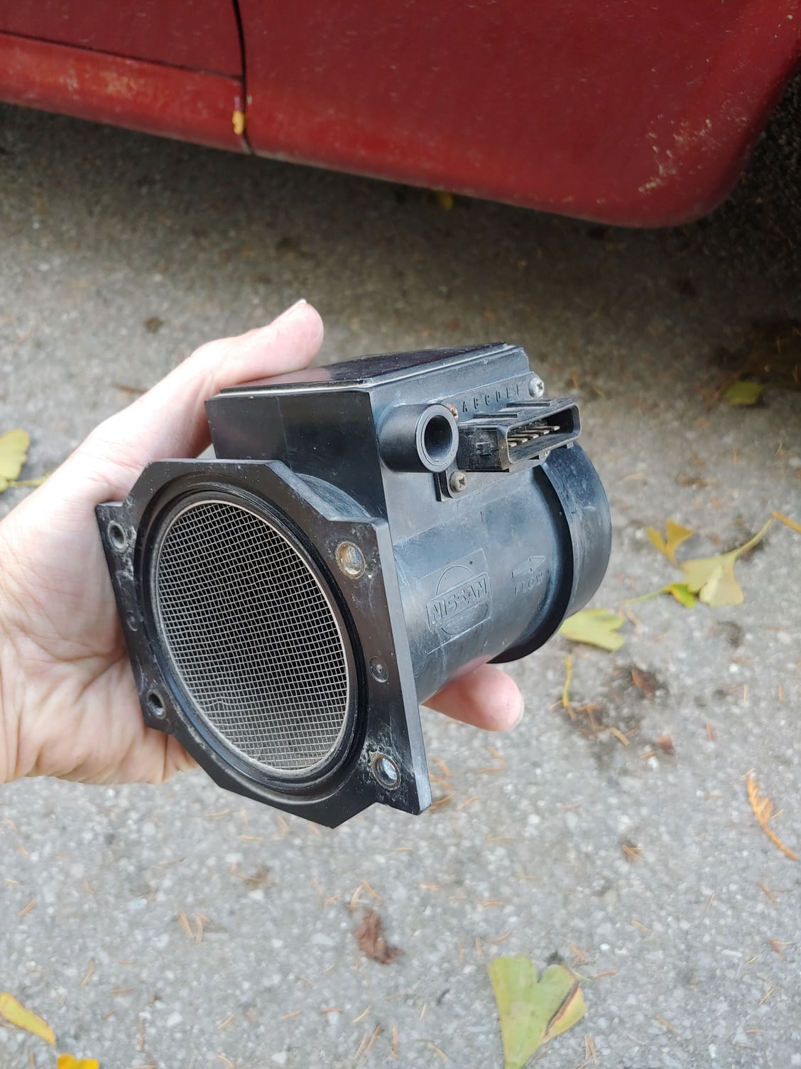
With that knowledge I started to look at my MAF options. There are a ton of them out there but I decided on the MAF from a Z32 300ZX. This was for two reasons: The flow curve is known and available online, the outlet is the same size as the stock intake tubing, and the inlet looked suspiciously like the stock Rx7 flange. Turns out none of these panned out the way I wanted, so I'll make it short and say that you are probably better off with an R35 MAF in a custom housing. I'll explain more about that later on.

Stock Rx7 MAFs were not an option for me. S4 has the flapper door style which adds restriction (probably not a ton, but enough that I noticed when I removed my old one) and S5 is marginally better with the sliding cone but still not as good as a hot-wire style MAF.

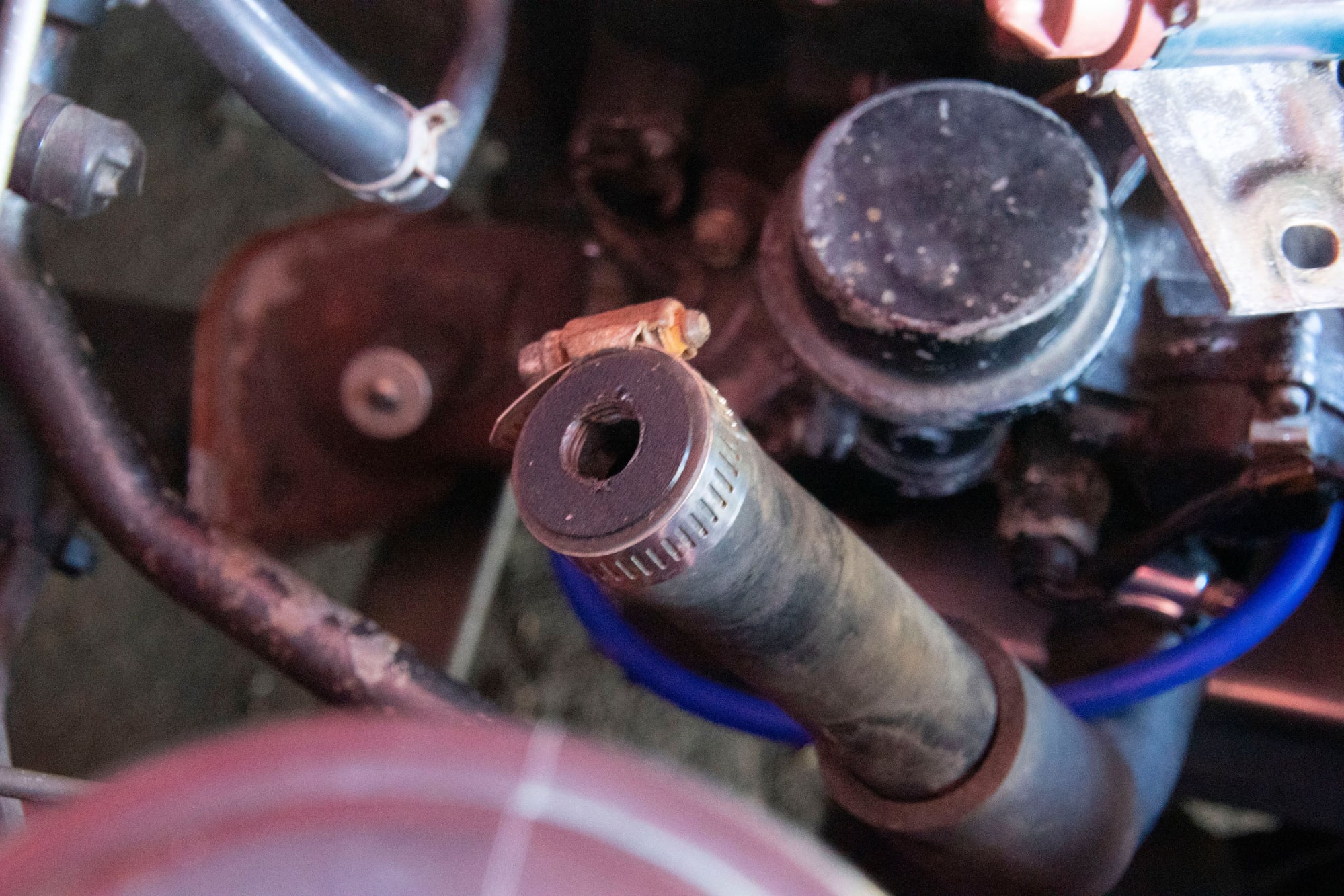
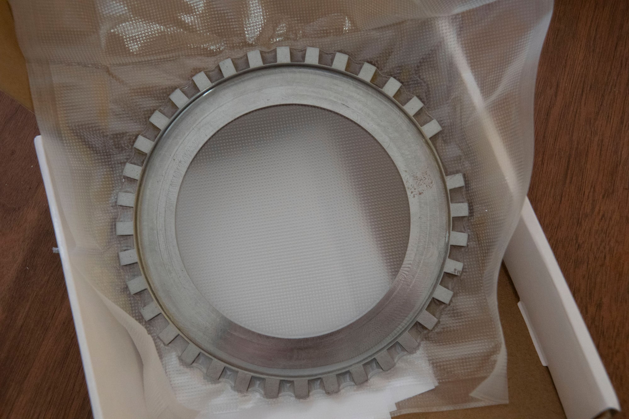
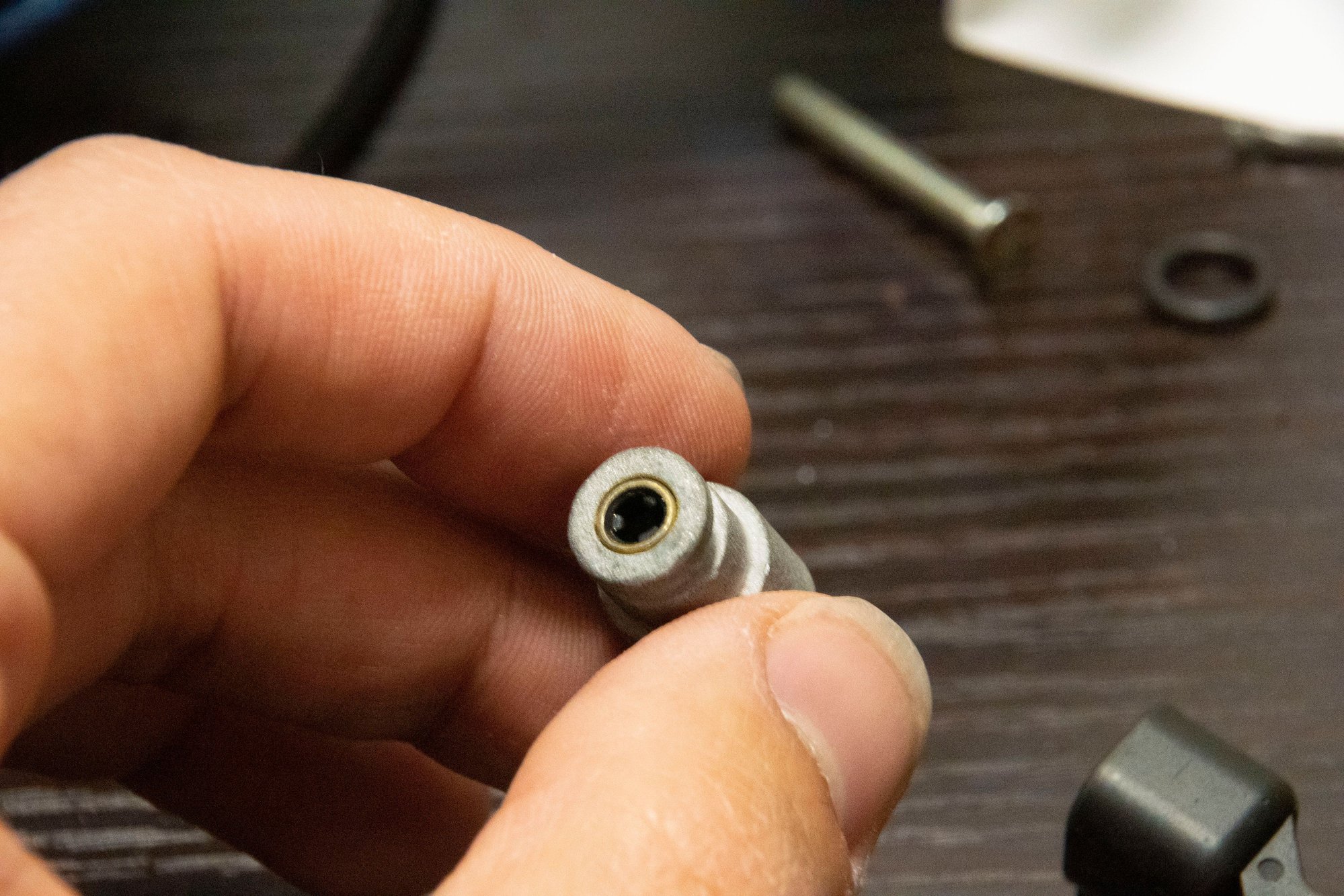
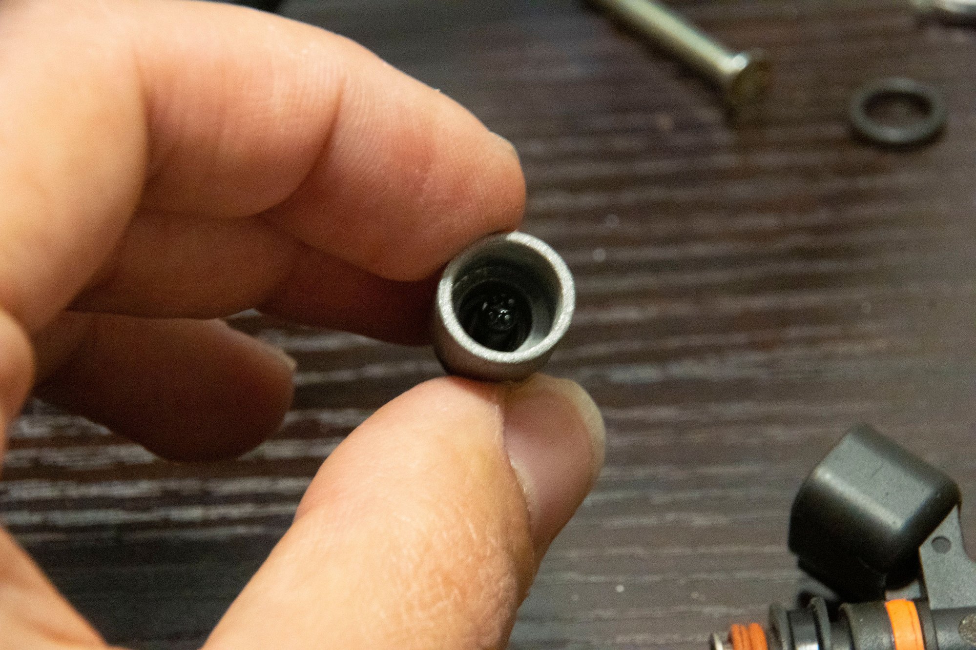
I ordered a used OEM Z32 MAF on eBay (don't buy the knockoff ones that are of dubious quality):


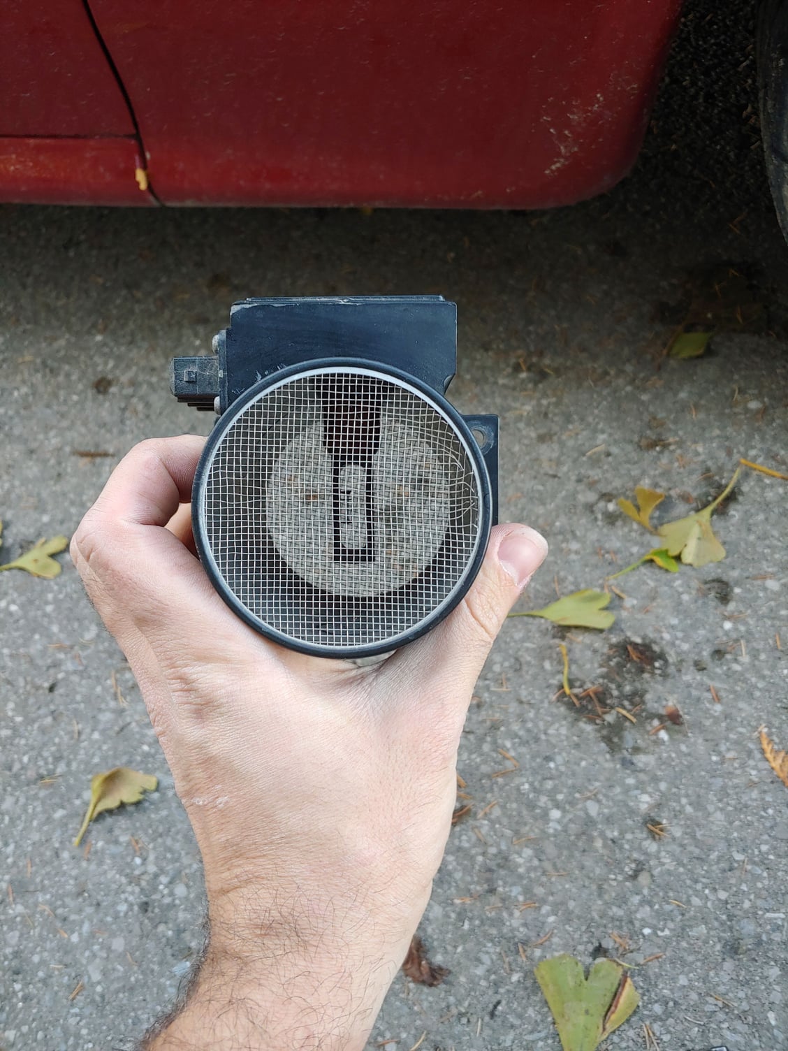
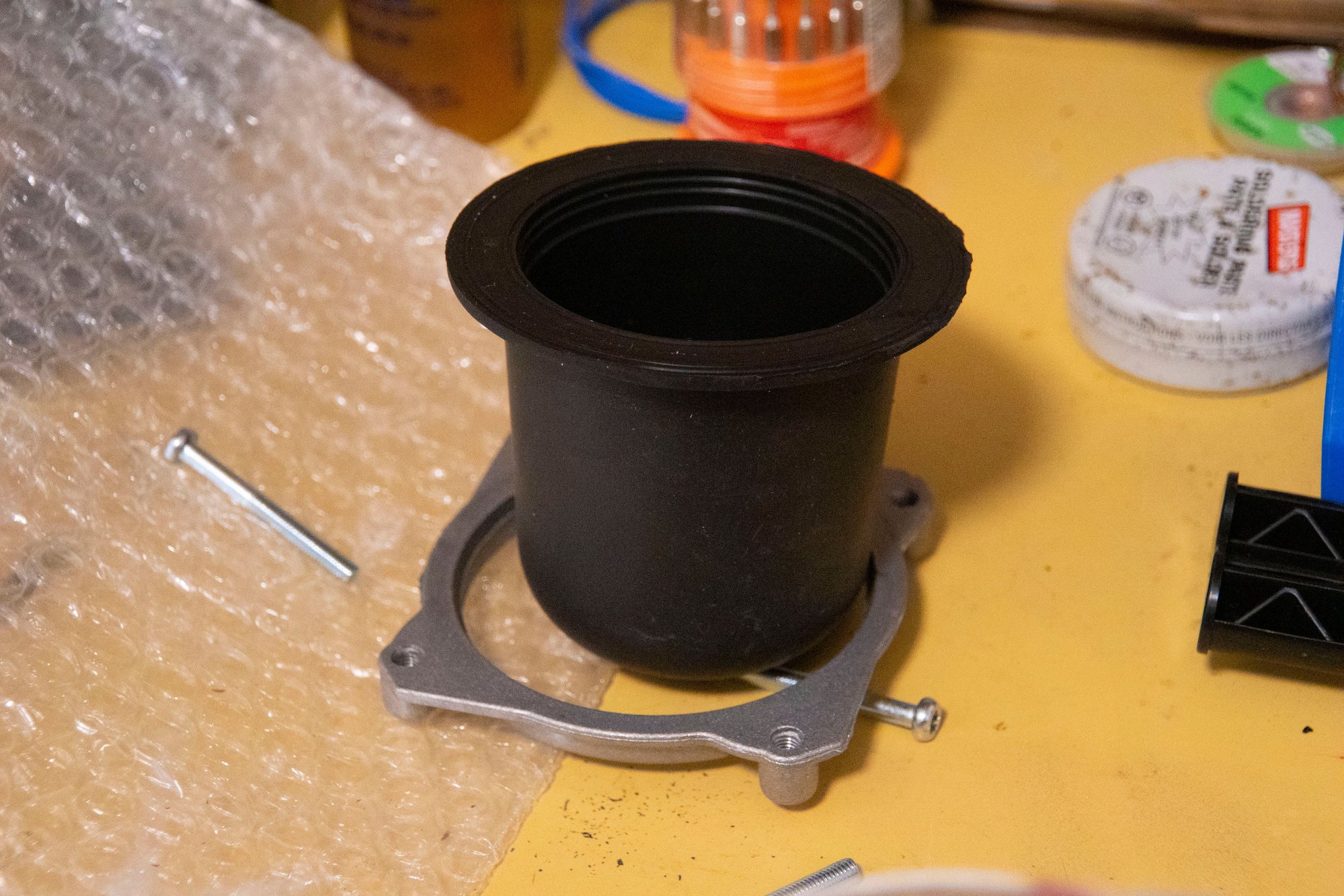
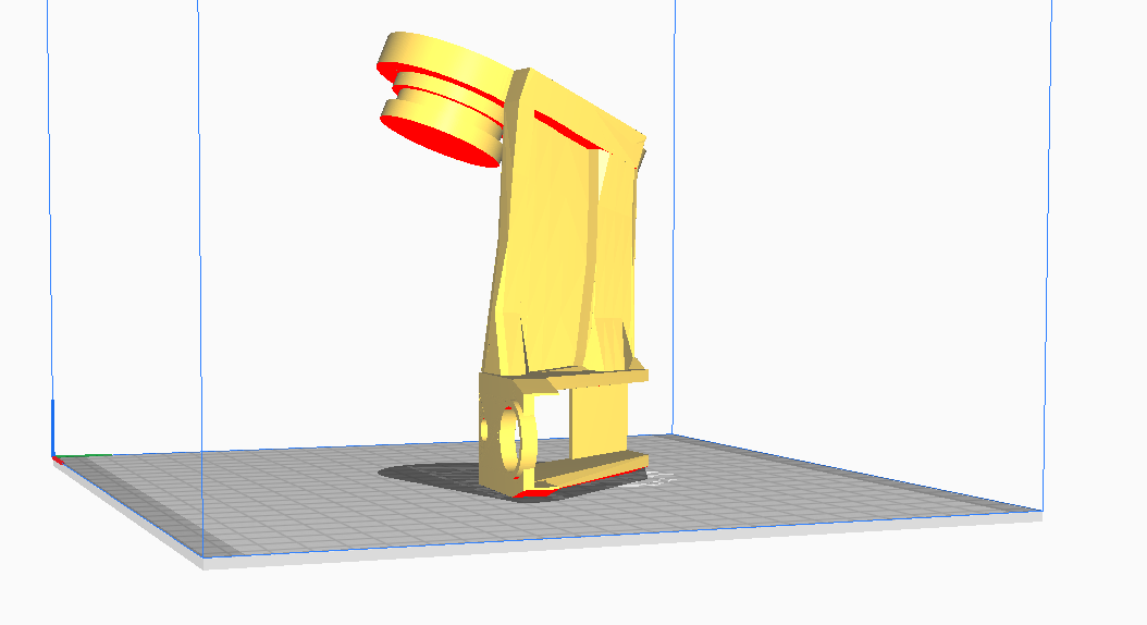
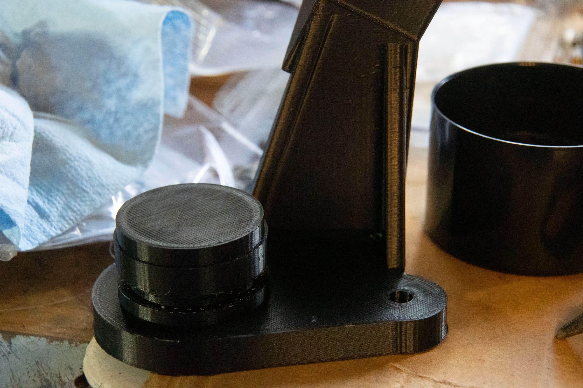
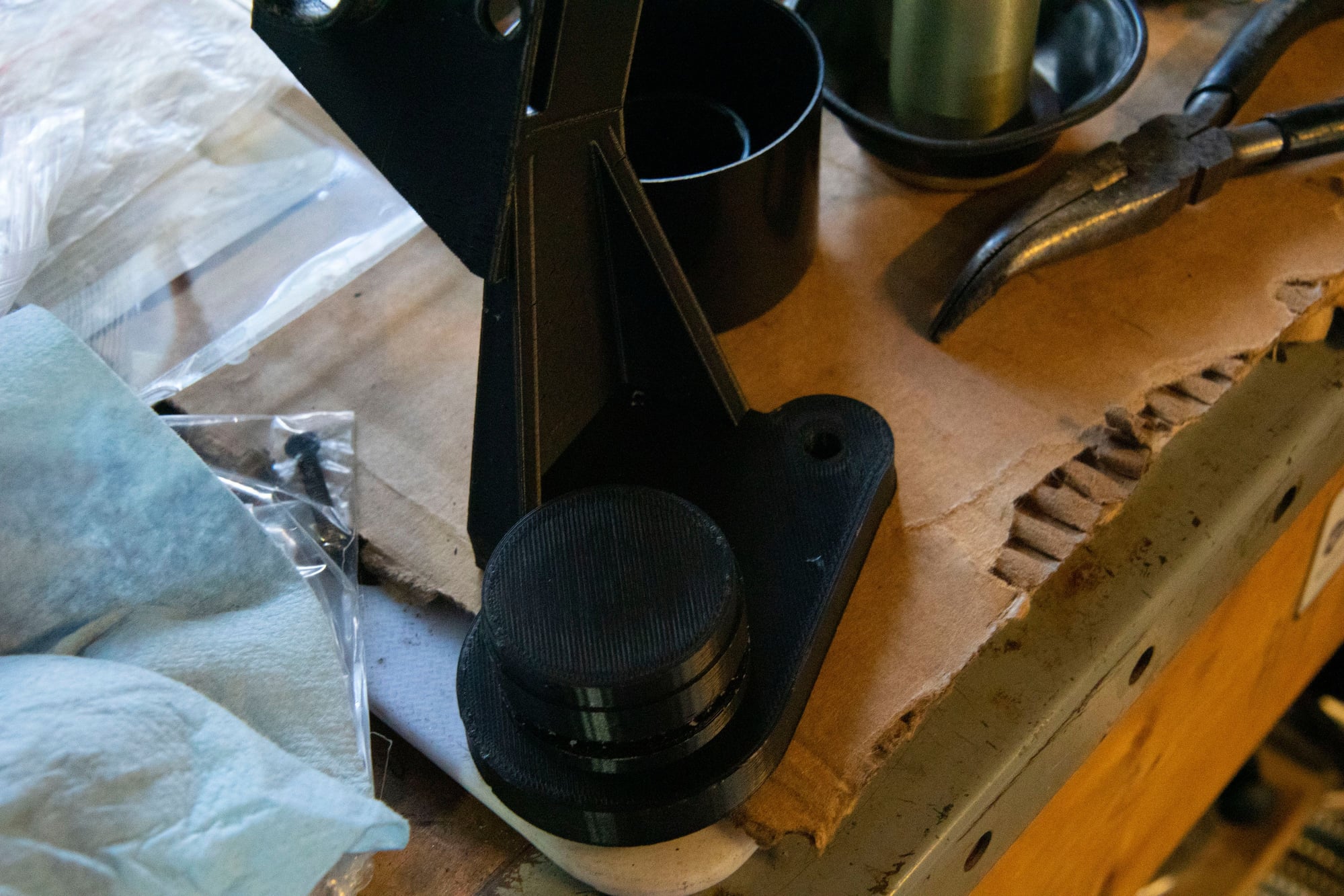
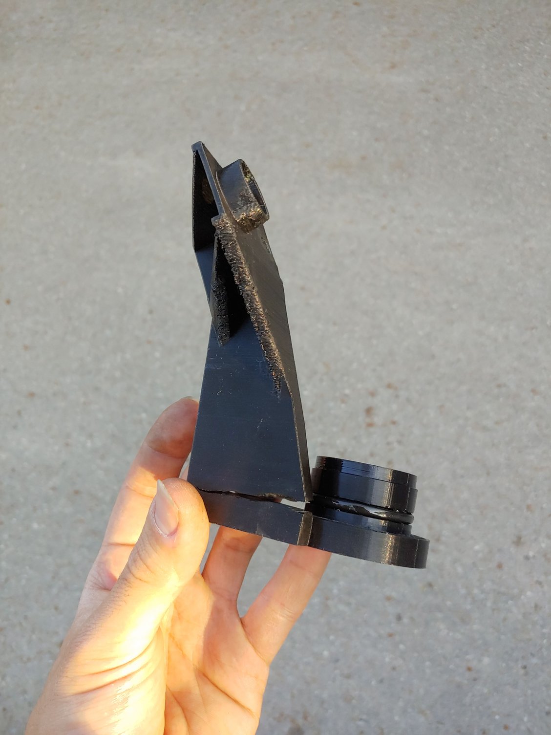
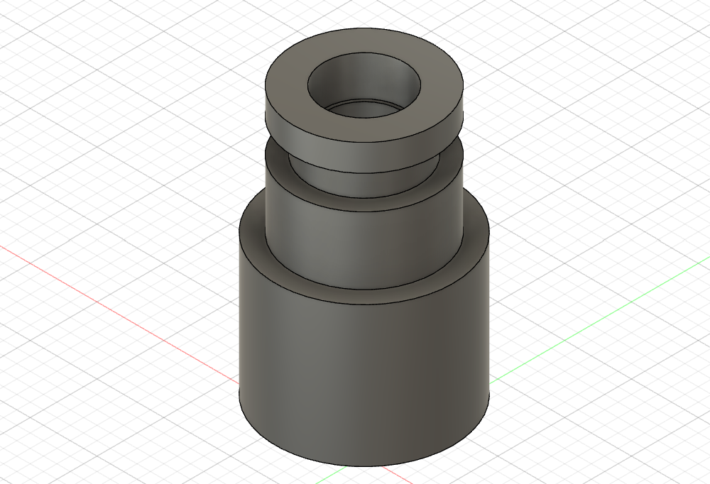
The mesh is a little wonky, but that doesn't really matter. You can see the hot wire in the center in that little plastic housing. However, I did notice a couple of things. The first was that the bolt pattern didn't match up at all with the stock airbox, and the second was that even if it did the MAF would be too short to reach the intake tubing. This meant an adapter would be required:


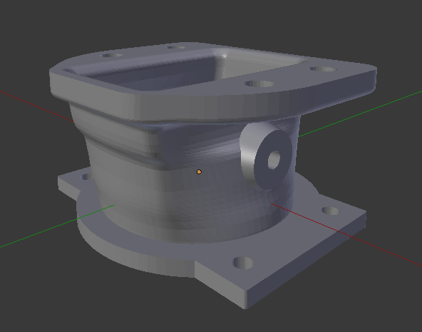
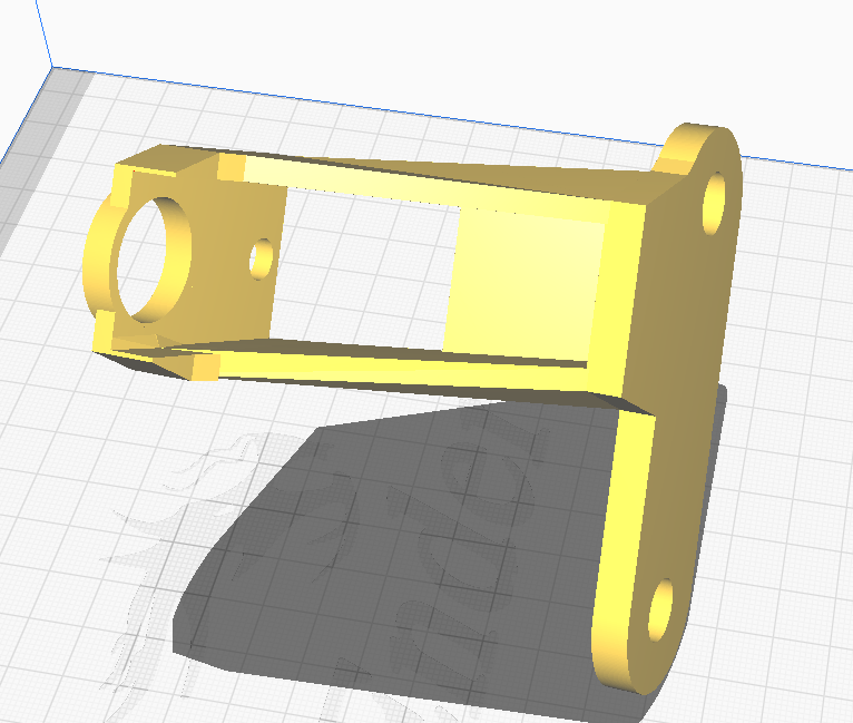
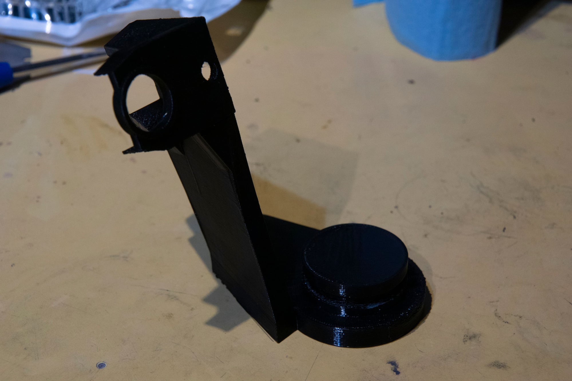
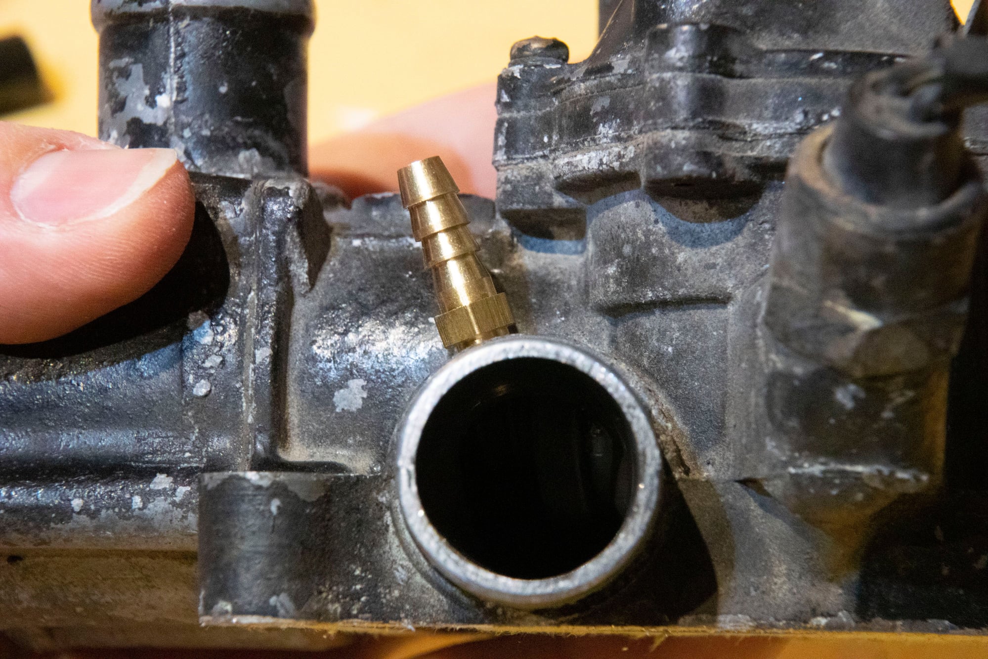
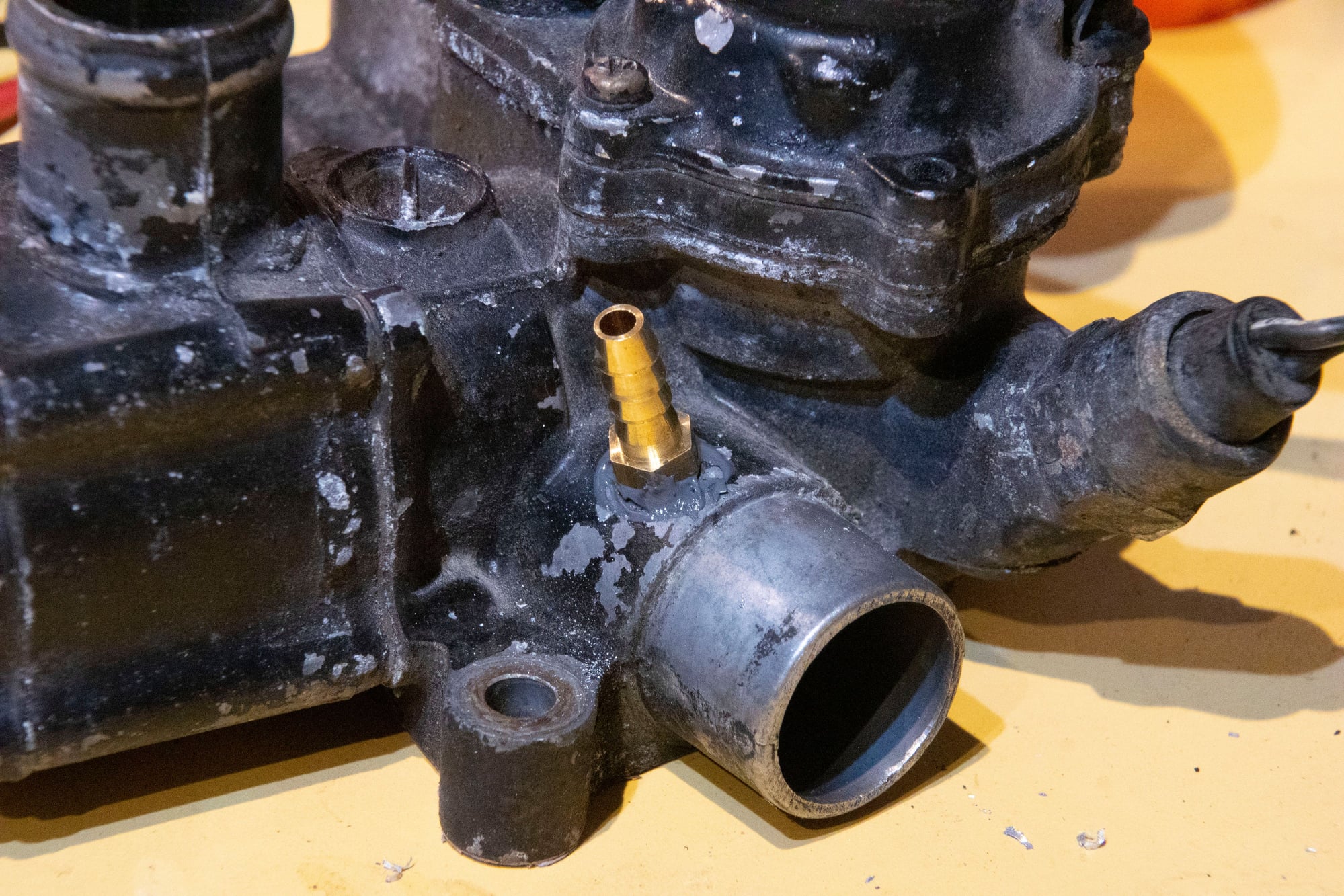
The one side is adapted from an existing model on Thingiverse that I had been using to replace the MAF with a tube. The other side has the bolt-pattern necessary to adapt to the Z32 inlet flange. There's also a small mounting boss for my IAT sensor, since I find putting it here is more accurate than the manifolds due to heat-soak.

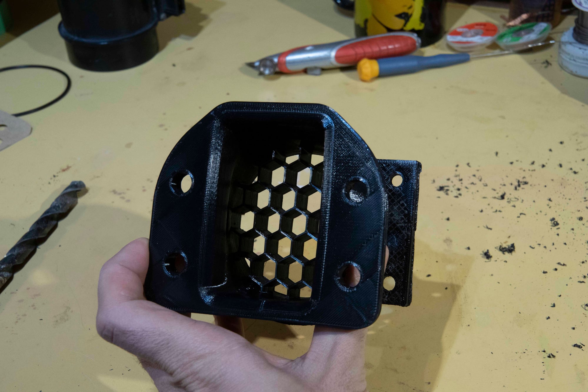
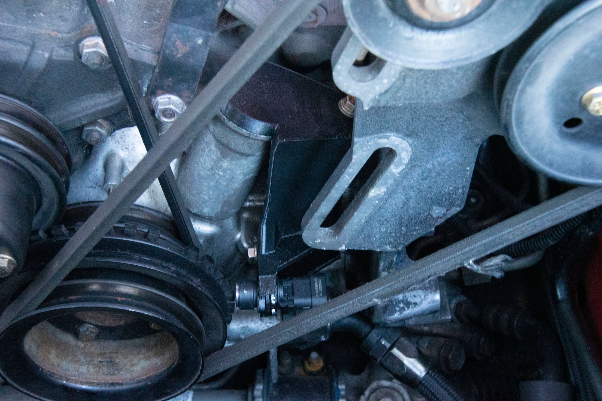
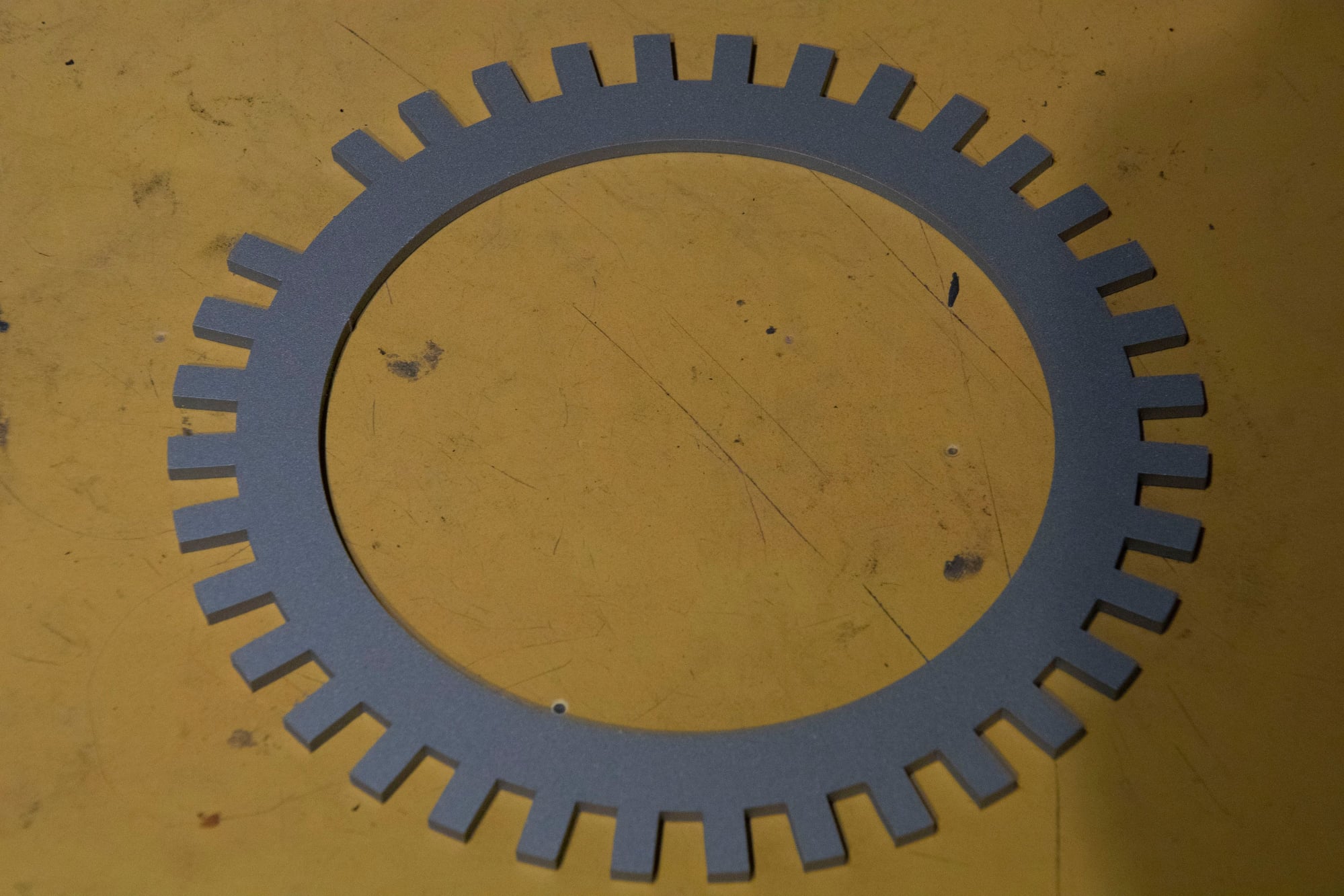
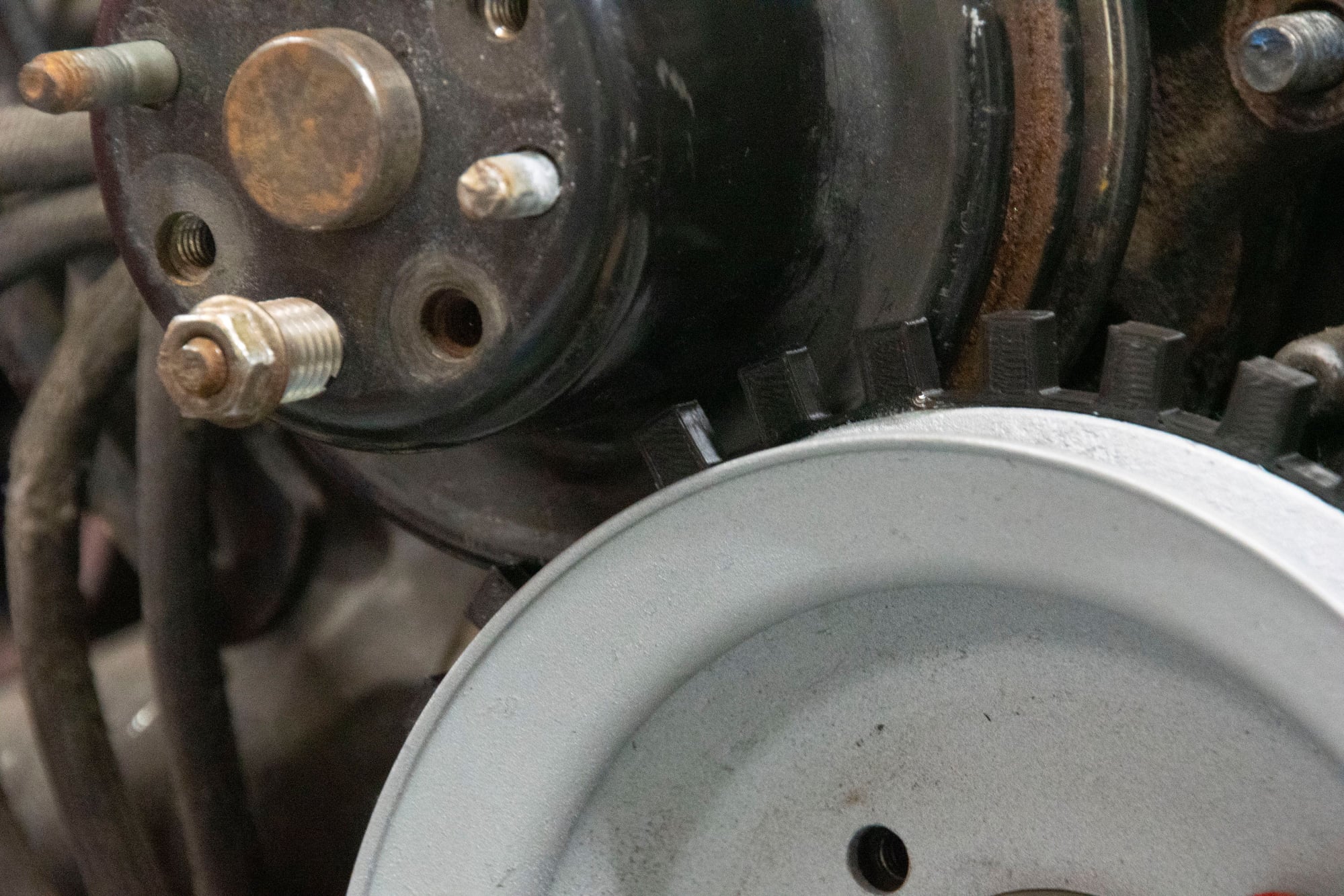
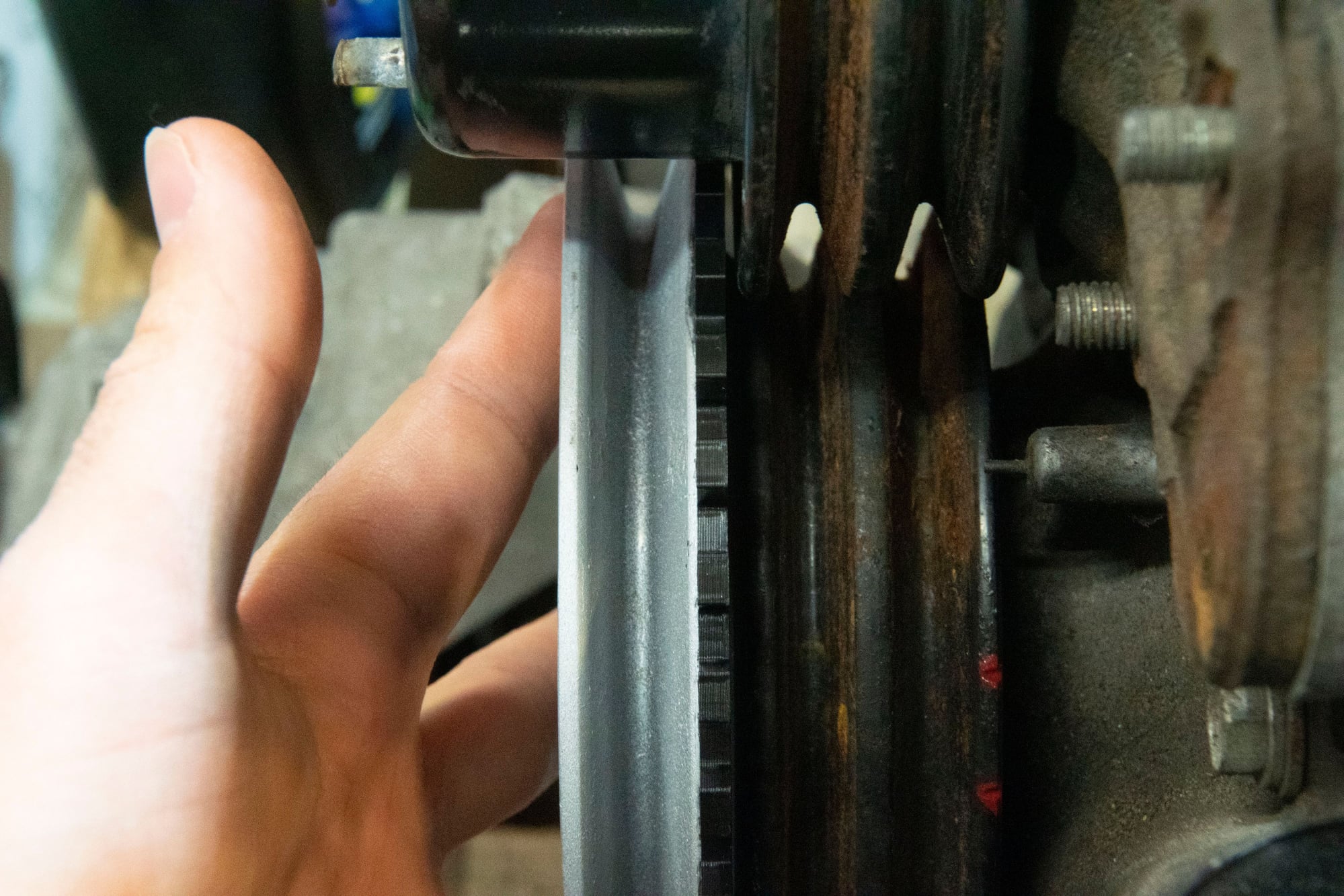
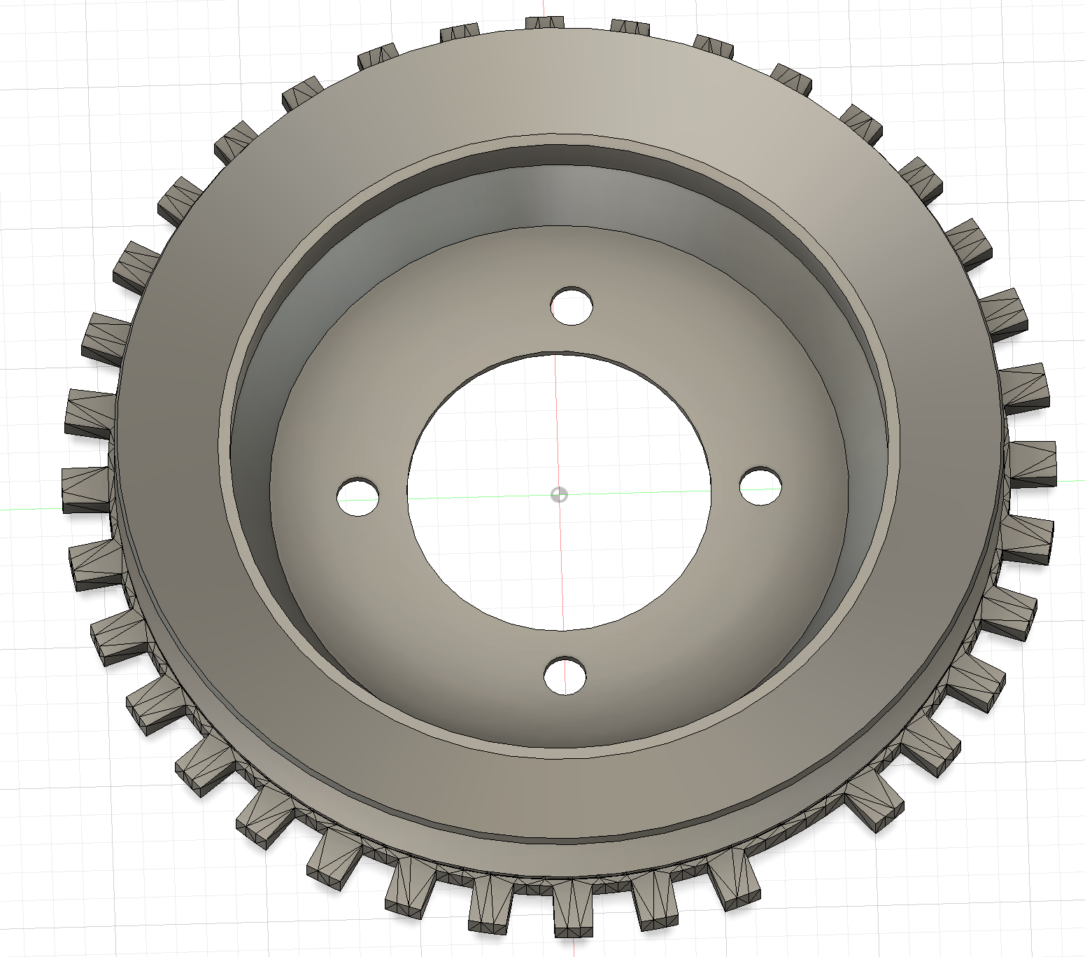
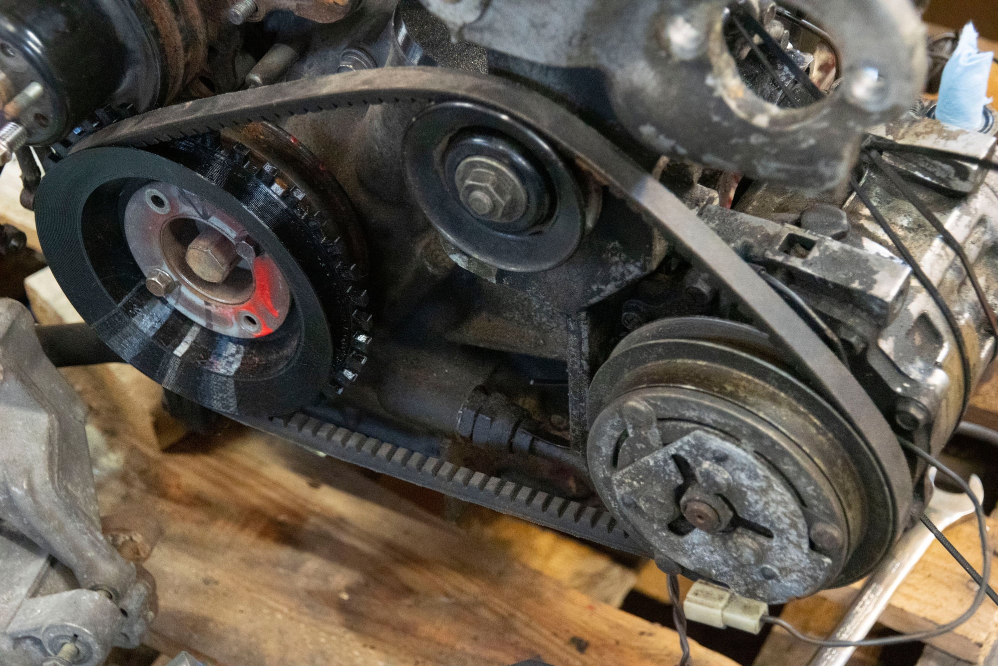
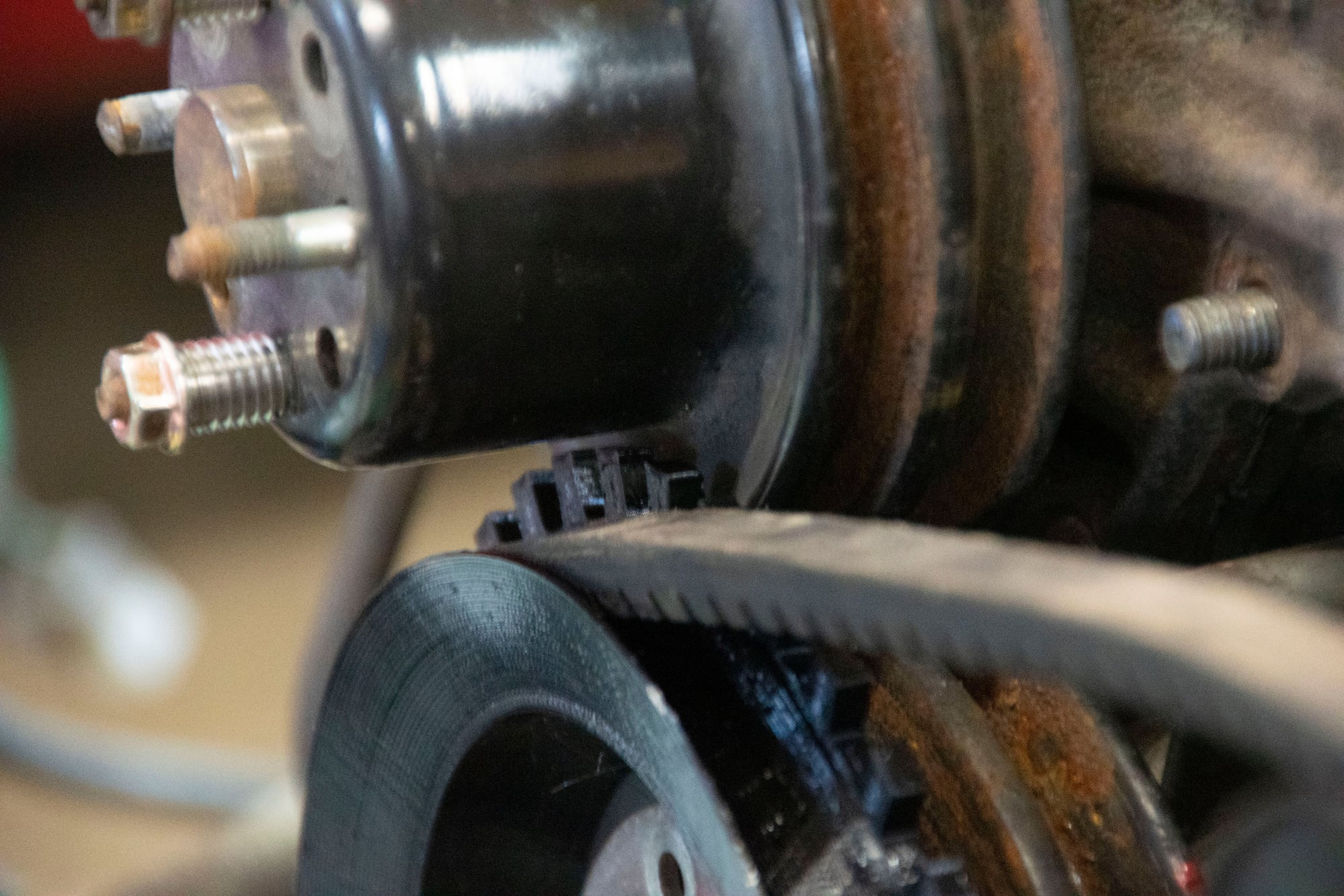
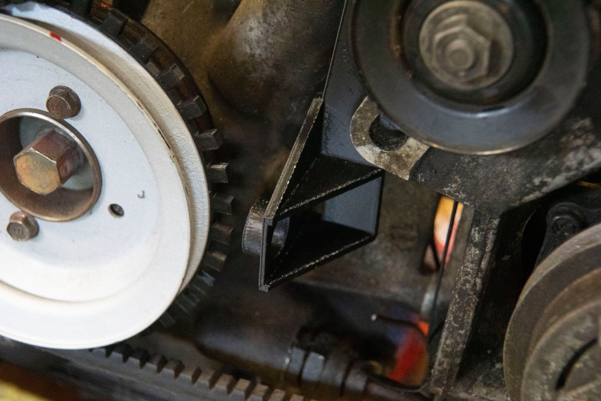
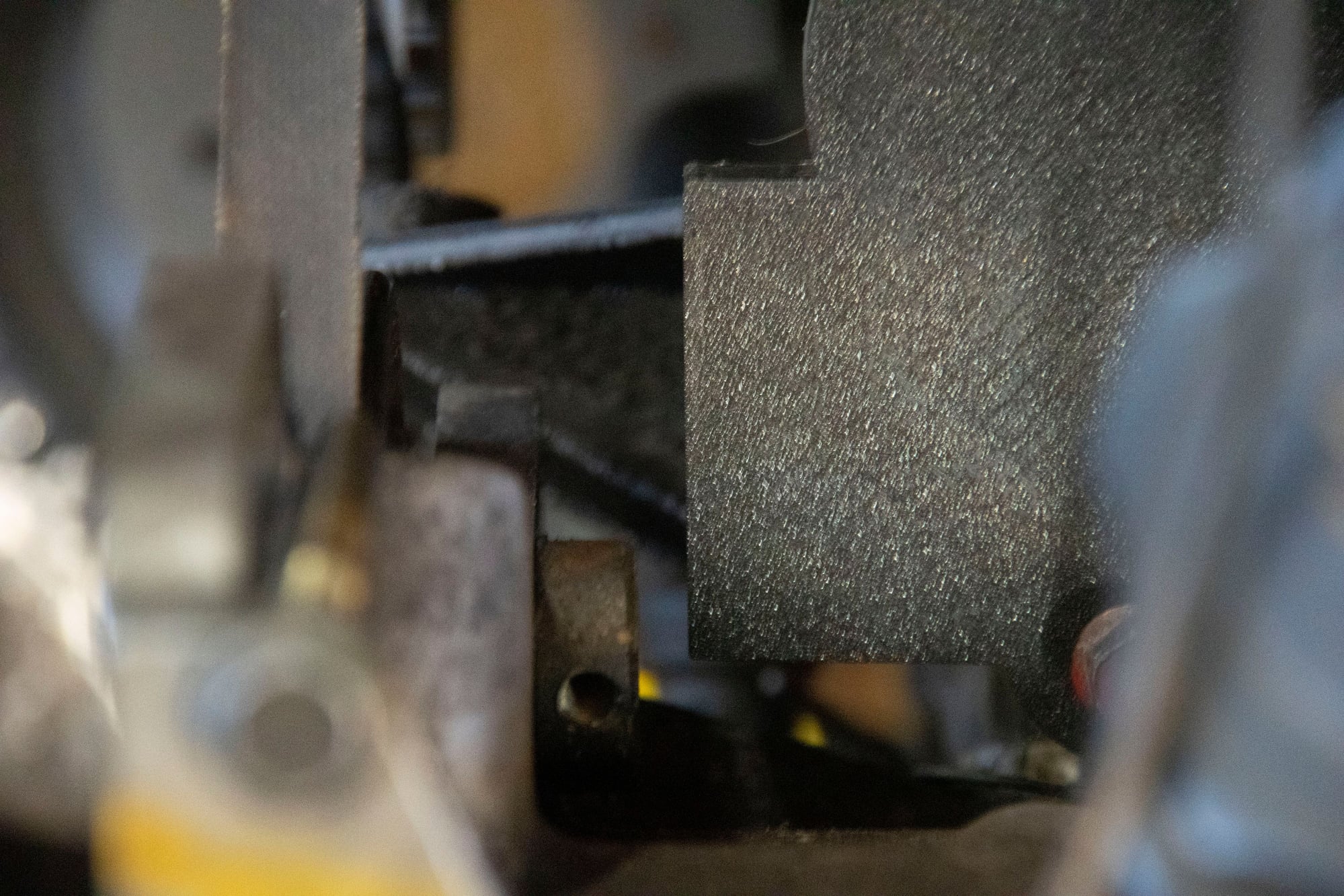
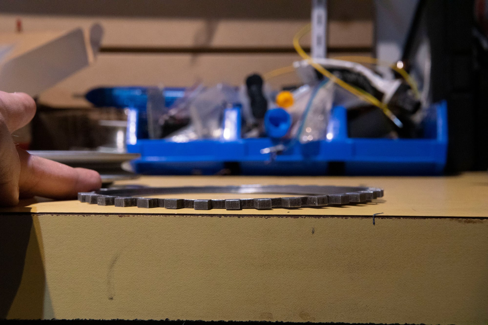
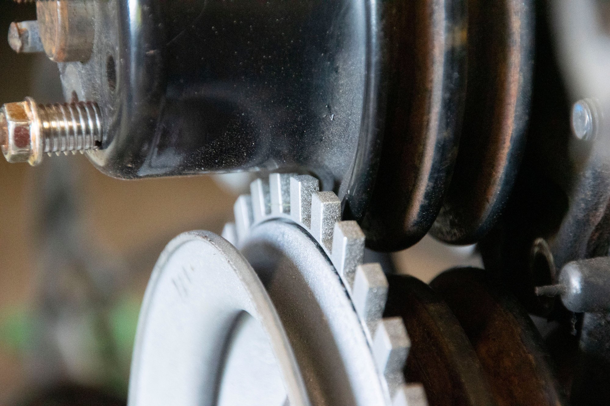
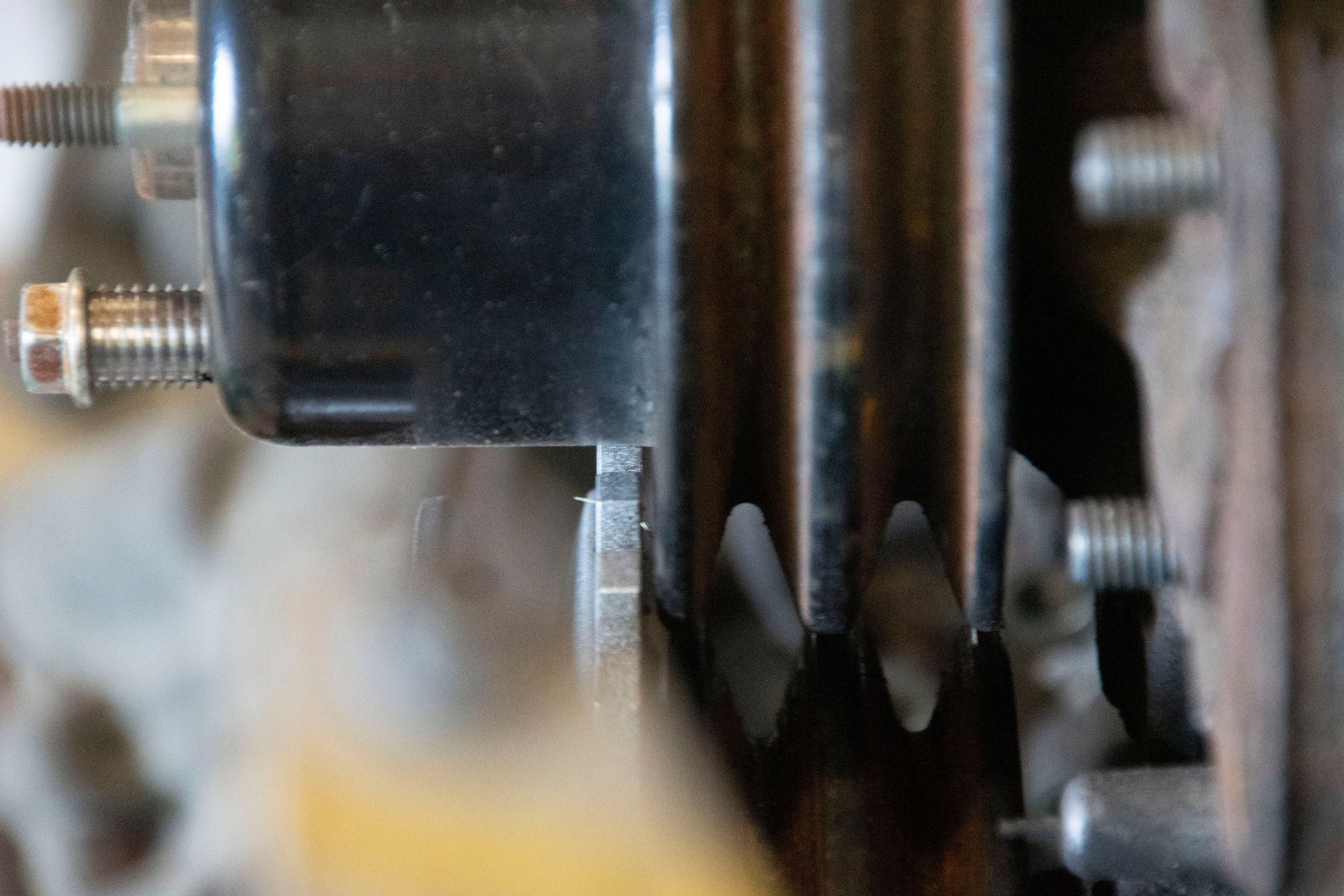
If you're wondering what's up with the honeycomb shape, that's a simple air-straightener I made. One thing I learned in the early testing stages was that airflow is super important with this style of MAF. The air should be in a straight tube the same diameter as the MAF for several inches before reaching the wire to ensure consistent even flow throughout the tube. If the airflow is swirling around, all one one side of the tube, or reverting back in the tube, these will cause the MAF to be way out of whack. The honeycomb shape was an attempt on my part to mitigate the challenge presented by the shape of the intake in this area. Take a look at what I mean:


That's actually an earlier revision of the adapter (and it required the MAF to be upside down), but it still illustrates my next point. The air in the airbox passes through the filter, then makes a sharp 90-degree turn through the outlet. Then it has about 7-8" of space to straighten out before reaching the MAF. This is obviously less than ideal in terms of ensuring even flow. Hence why the honeycomb was a necessary addition. I should also note that there are commercially available honeycombs for this purpose, usually with a much tighter diameter for the honeycomb cells. I couldn't fit one without making the adapter tube inside exactly cylindrical (resulting in a more abrupt transition), so I was limited by the 3d filament in terms of how thin I could make the walls of each cell in the honeycomb.

I think the only reason Mazda got away with their stock MAFs is that the design of the flapper-door and sliding-cone don't really care whether airflow is even. The amount of air passing by exerts some known amount of force on the door / cone, and this translates to the MAF reading. Done. Meanwhile with the hot-wire it can read low if the pipe is flowing a lot more air on one side, or bounce around if air is swirling a bit.

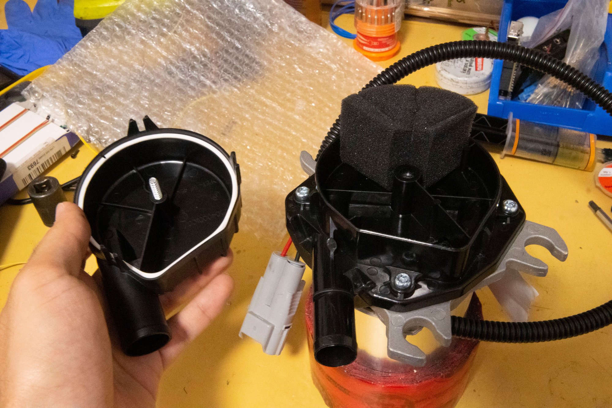
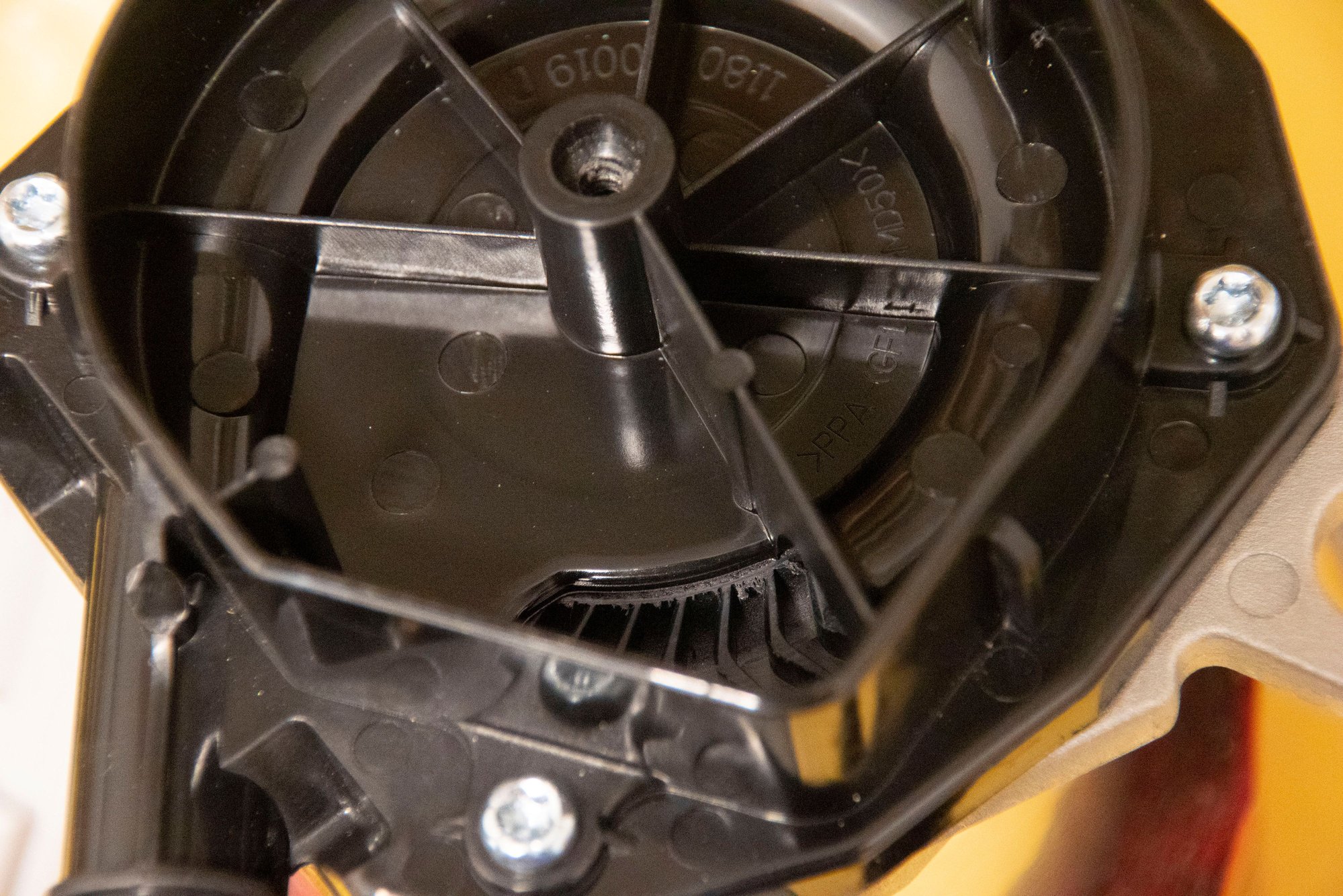
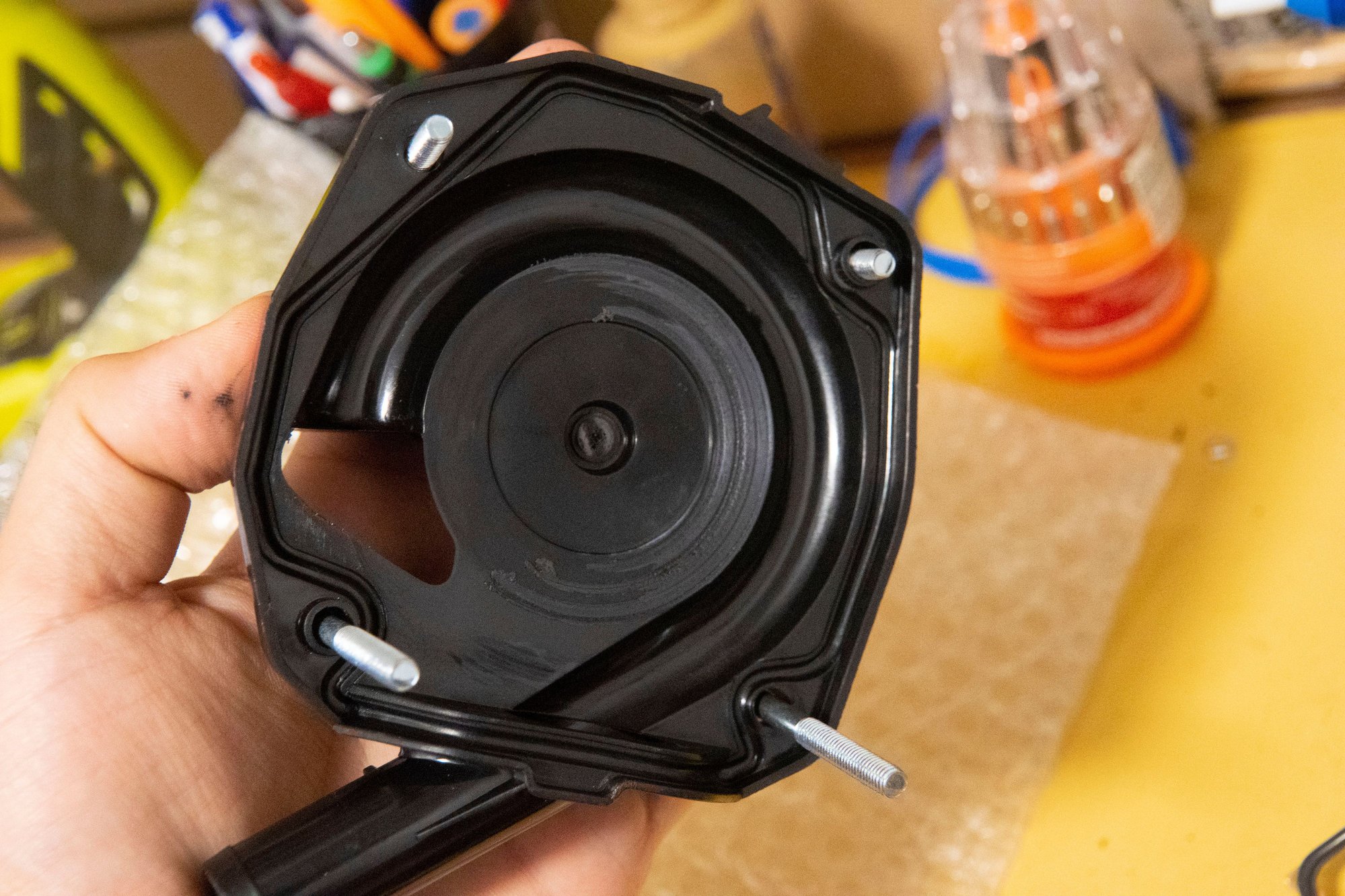
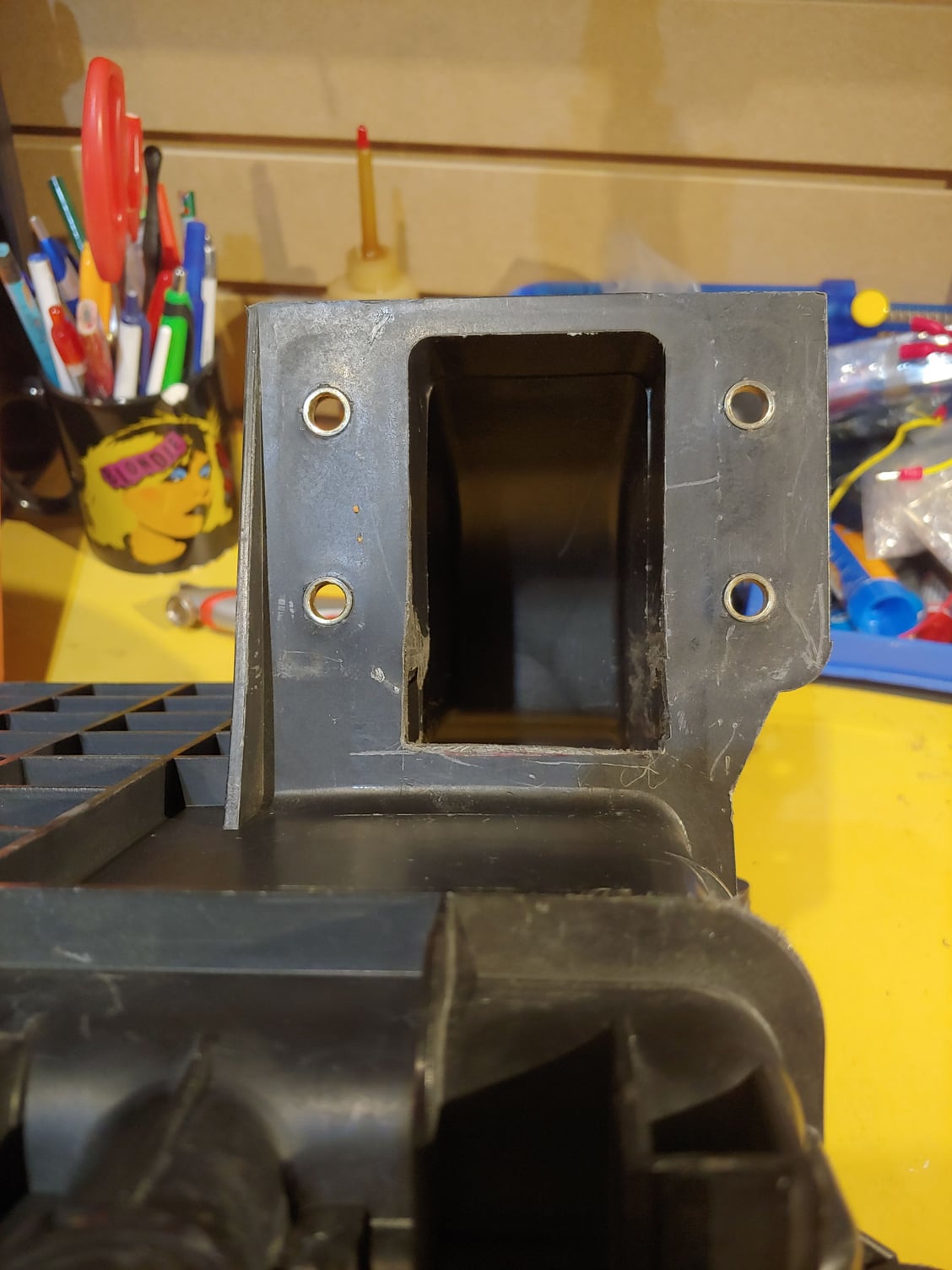
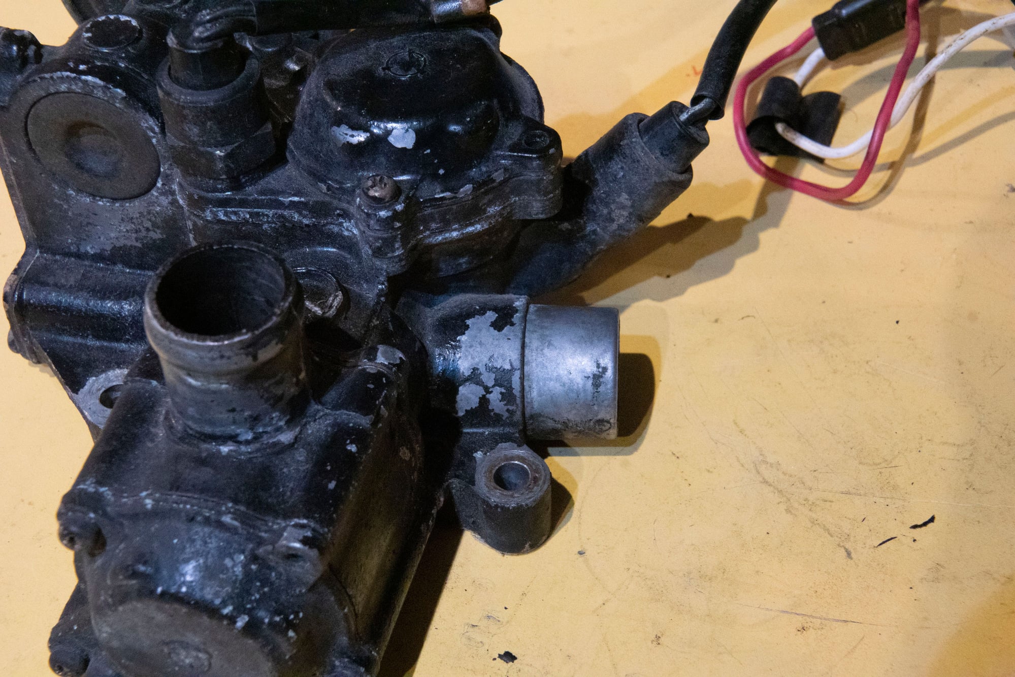
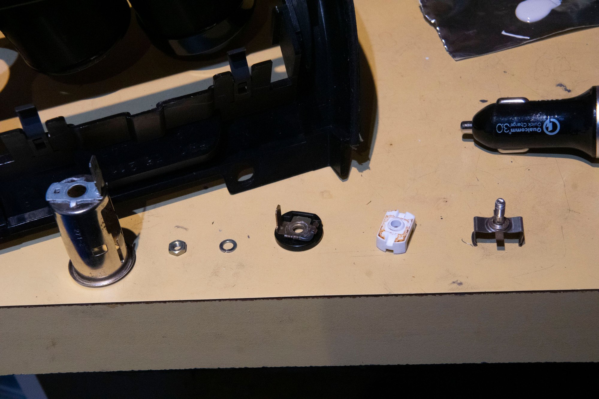
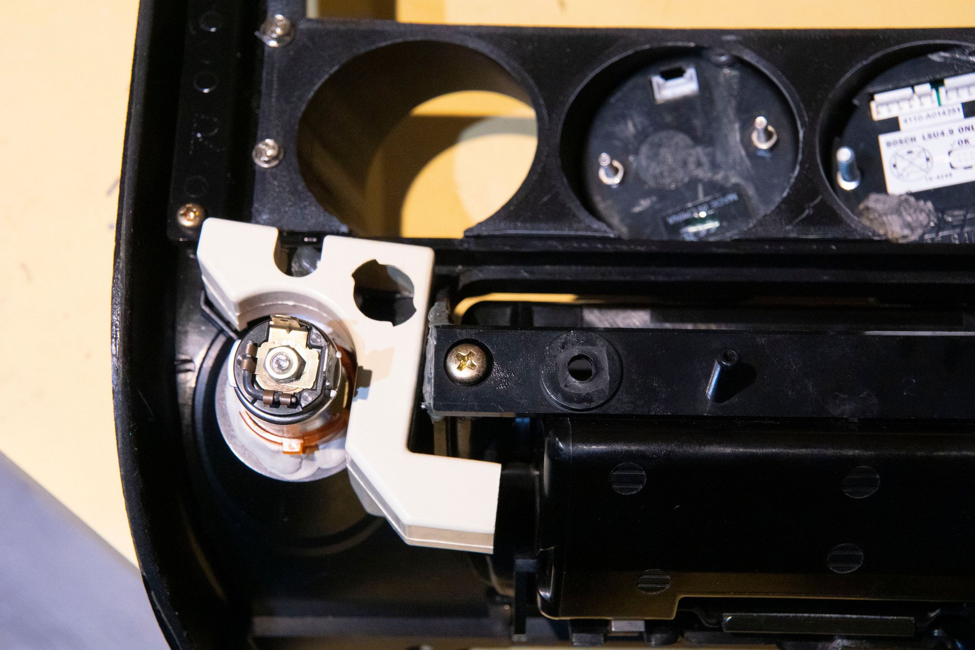
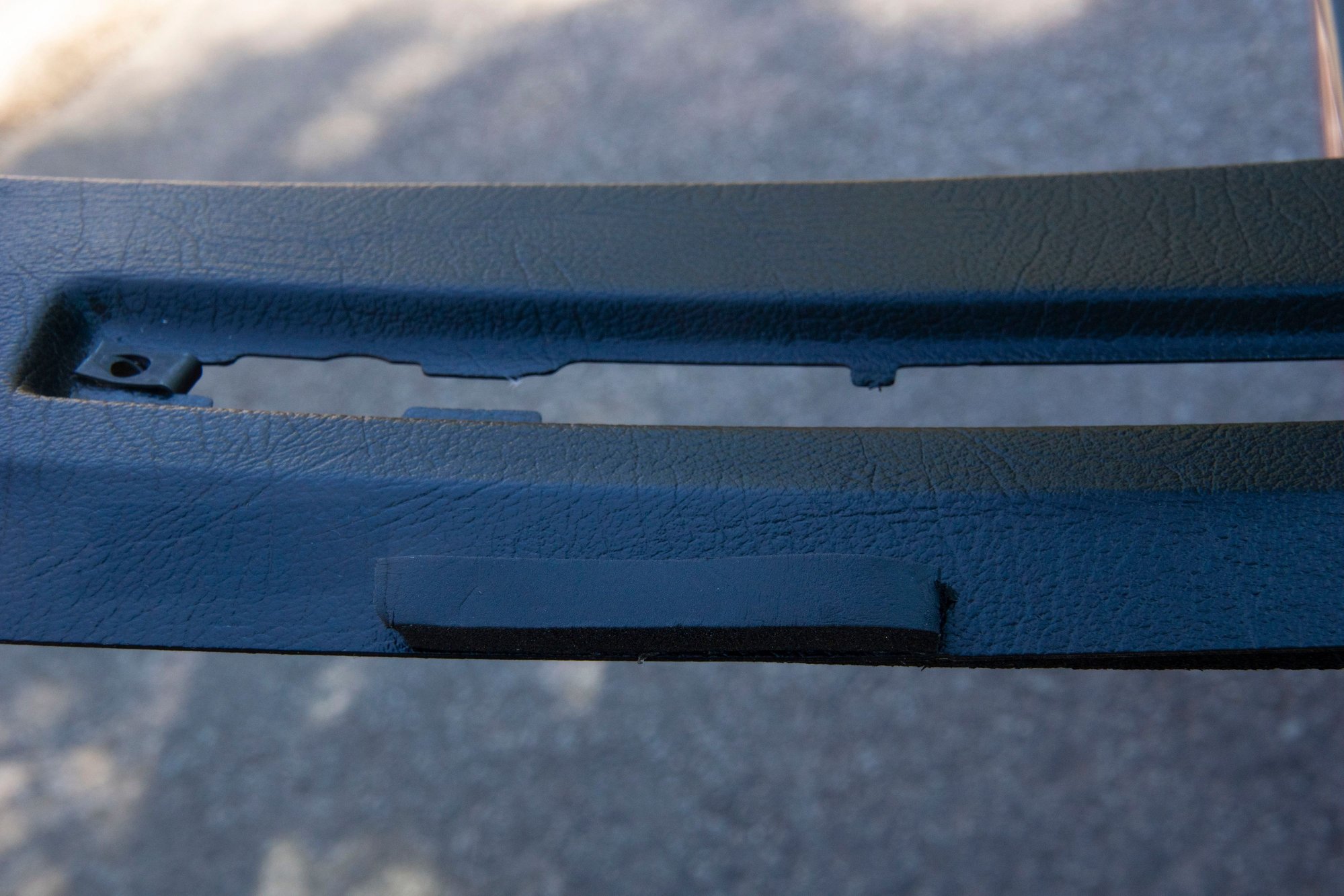
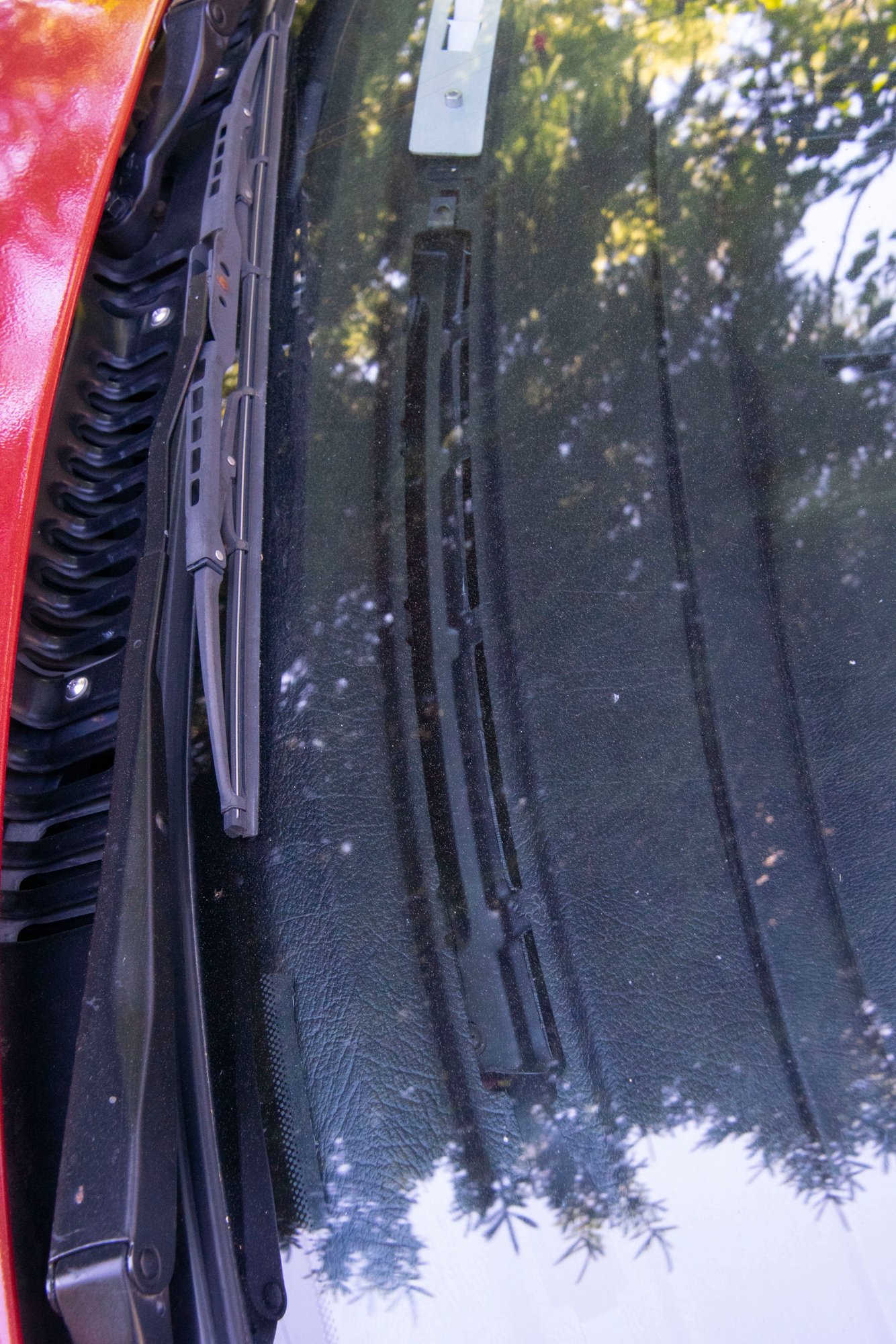
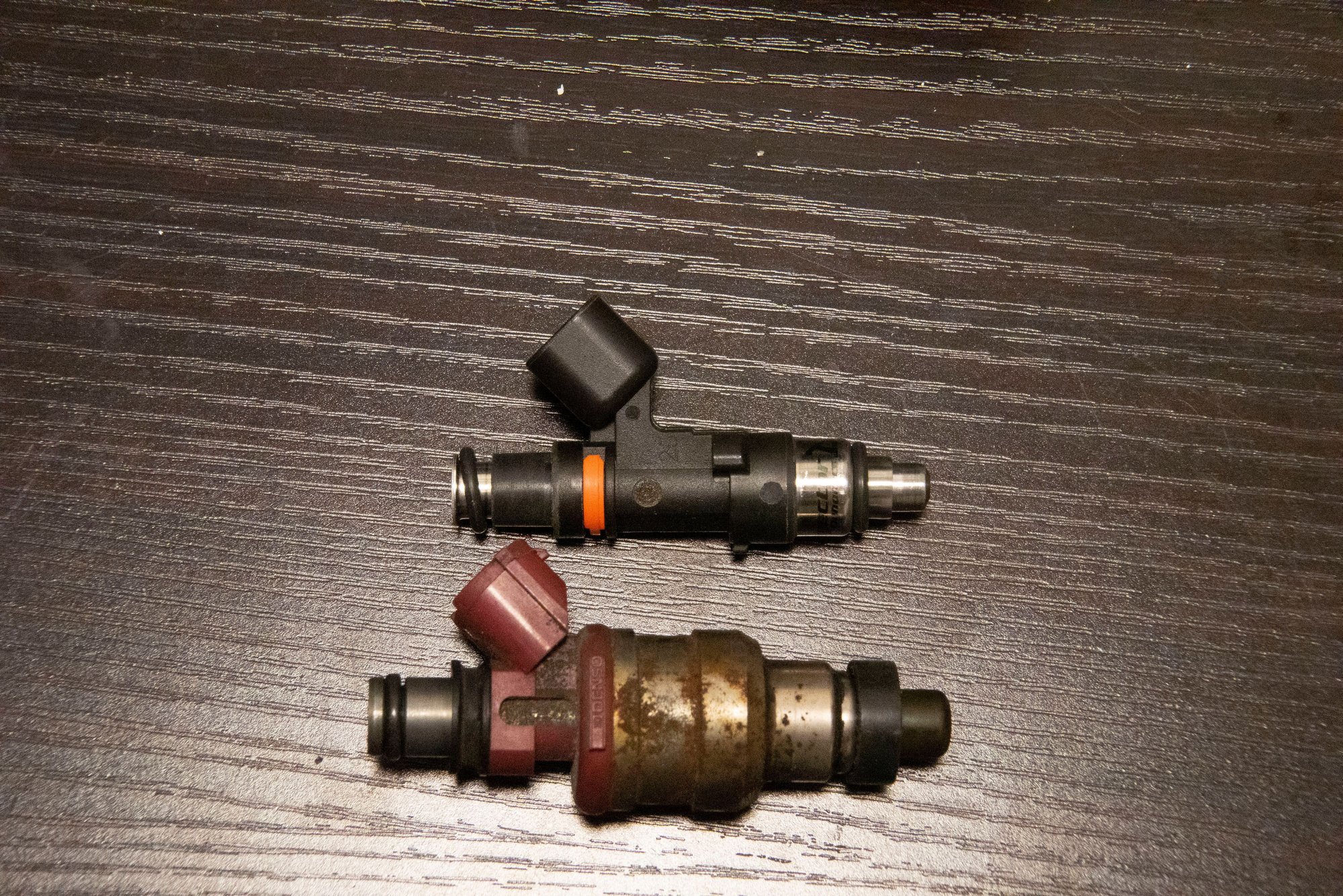
Speaking of Mazda's stock design, I also noticed something weird. The outlet of the airbox had this rectangular piece in it, reducing the surface area of the opening at the top of the outlet. I can only assume they wanted to use off-the-shelf Denso MAFs and decided the opening didn't need to be any bigger than the rectangular MAF inlet, which makes some sense. But now that I am not using the Denso MAF that restriction can go:


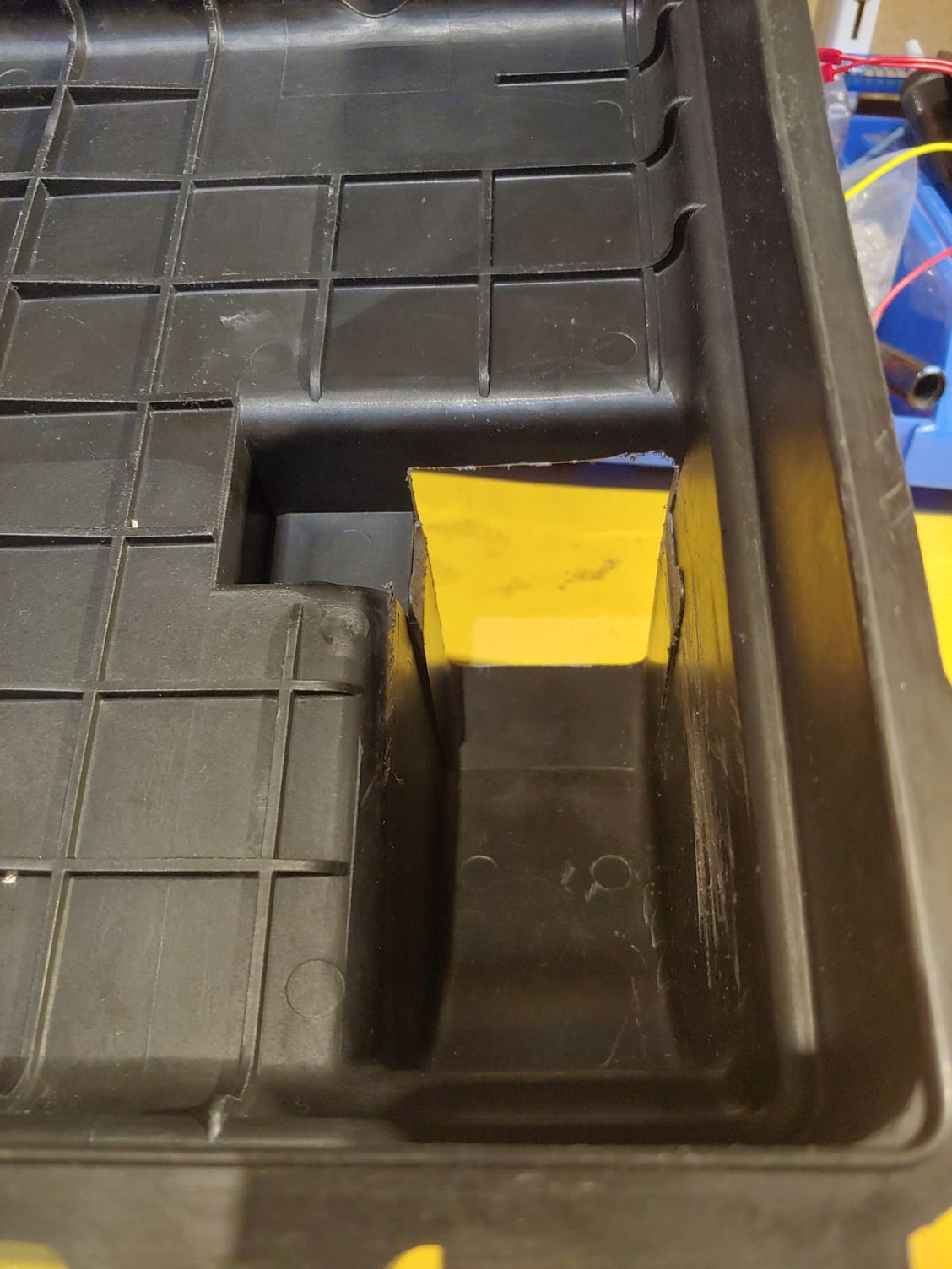
And the rectangular piece also covered this side near the filter:


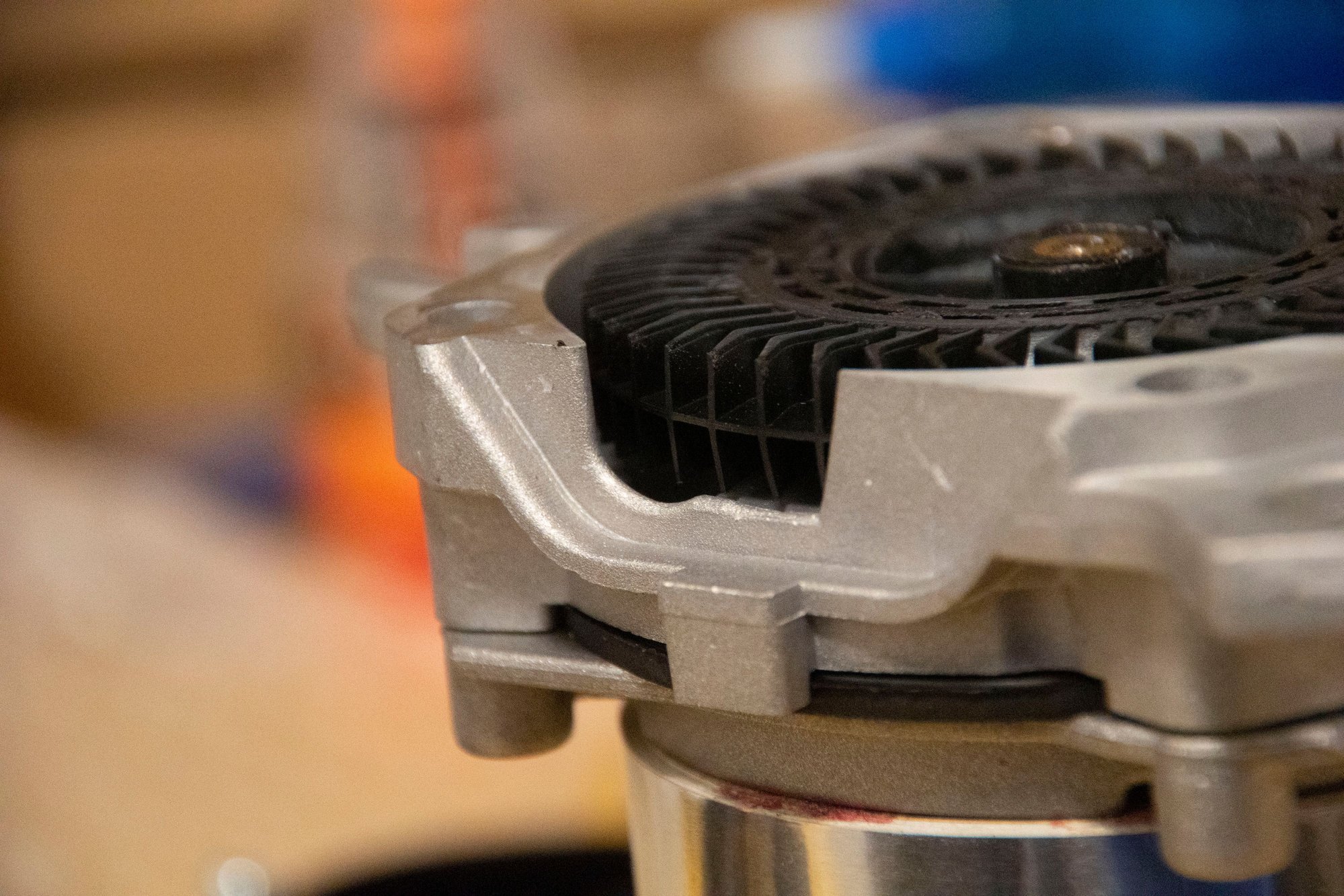
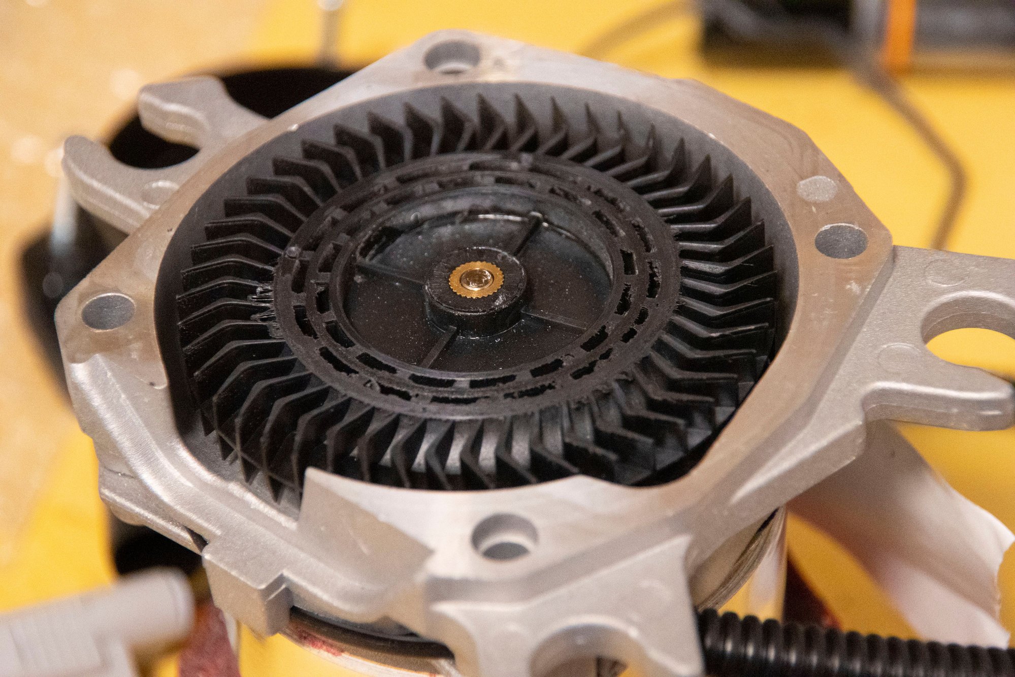
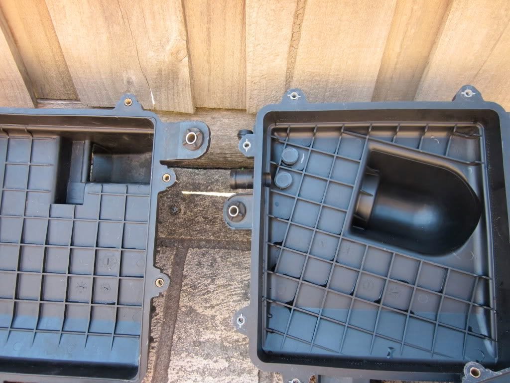
I found this picture that shows the original lip thing (left) as well as a comparison with the S5 airbox. The S5 has a much larger valley where it transitions from airbox to filter, and it's located more central to the filter as well. I kind of wonder if there are any more gains to be had here, but if there are I doubt it's anything substantial.


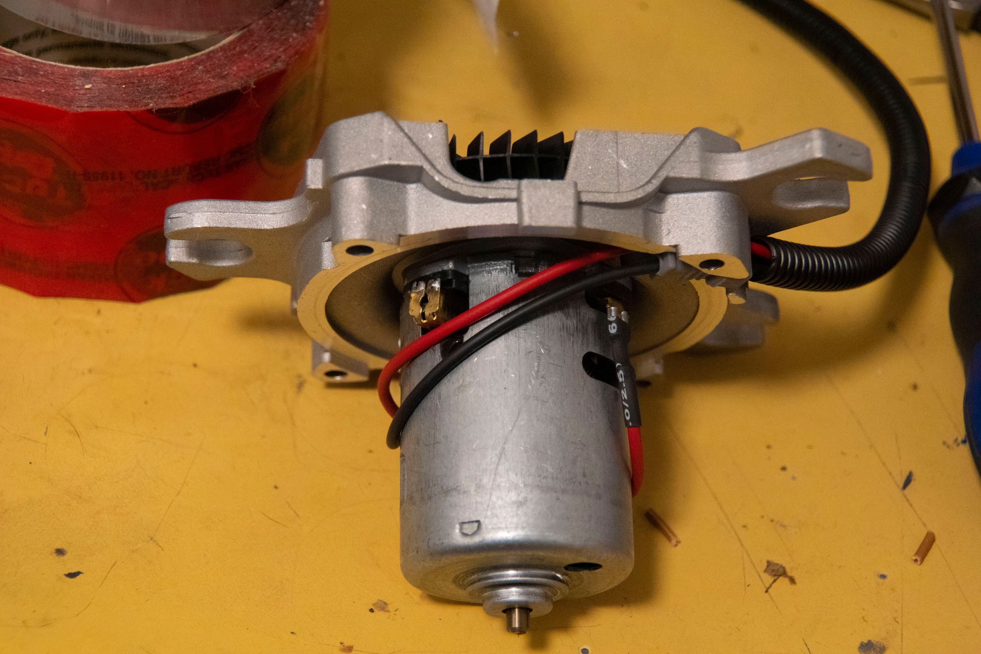
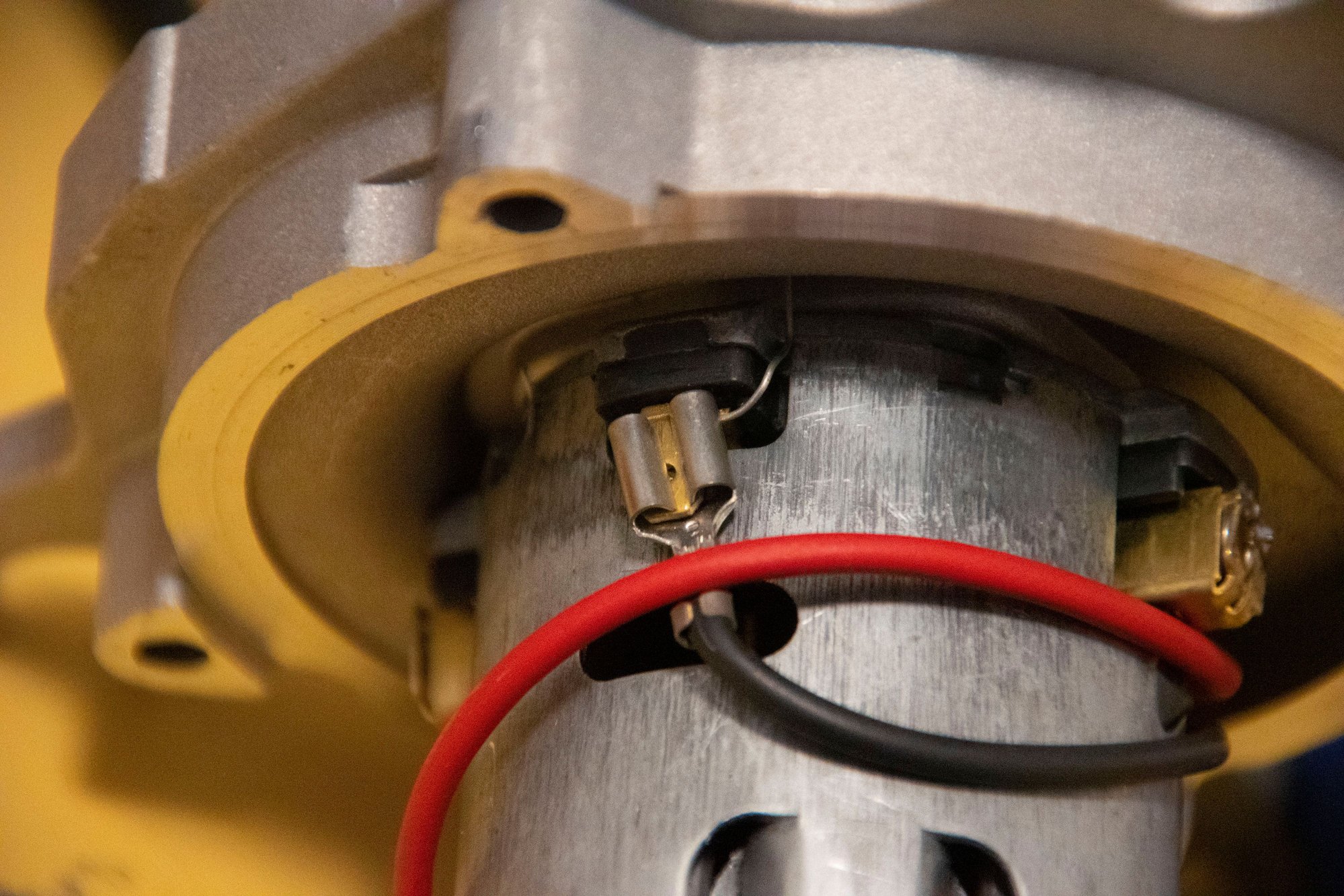
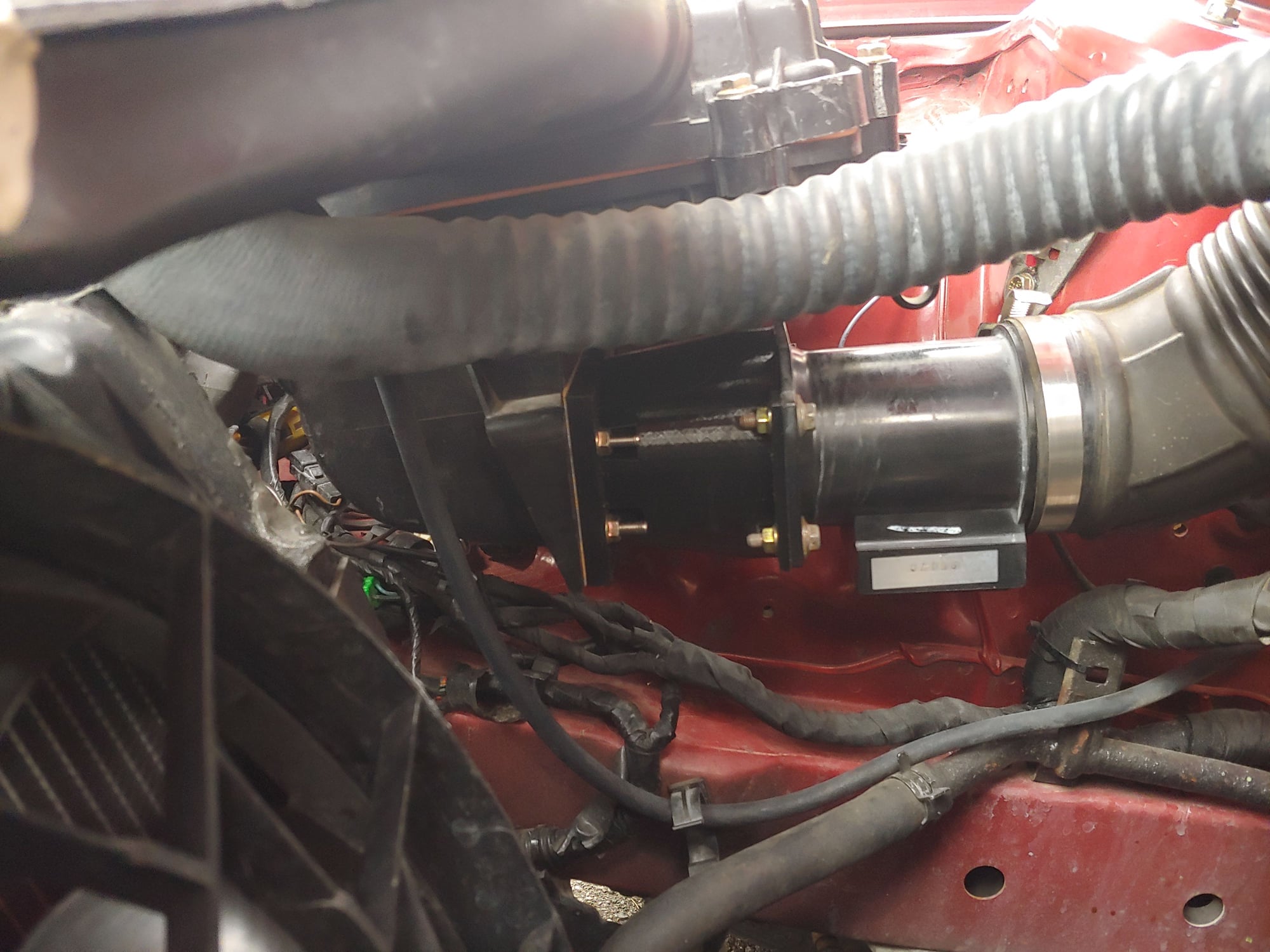
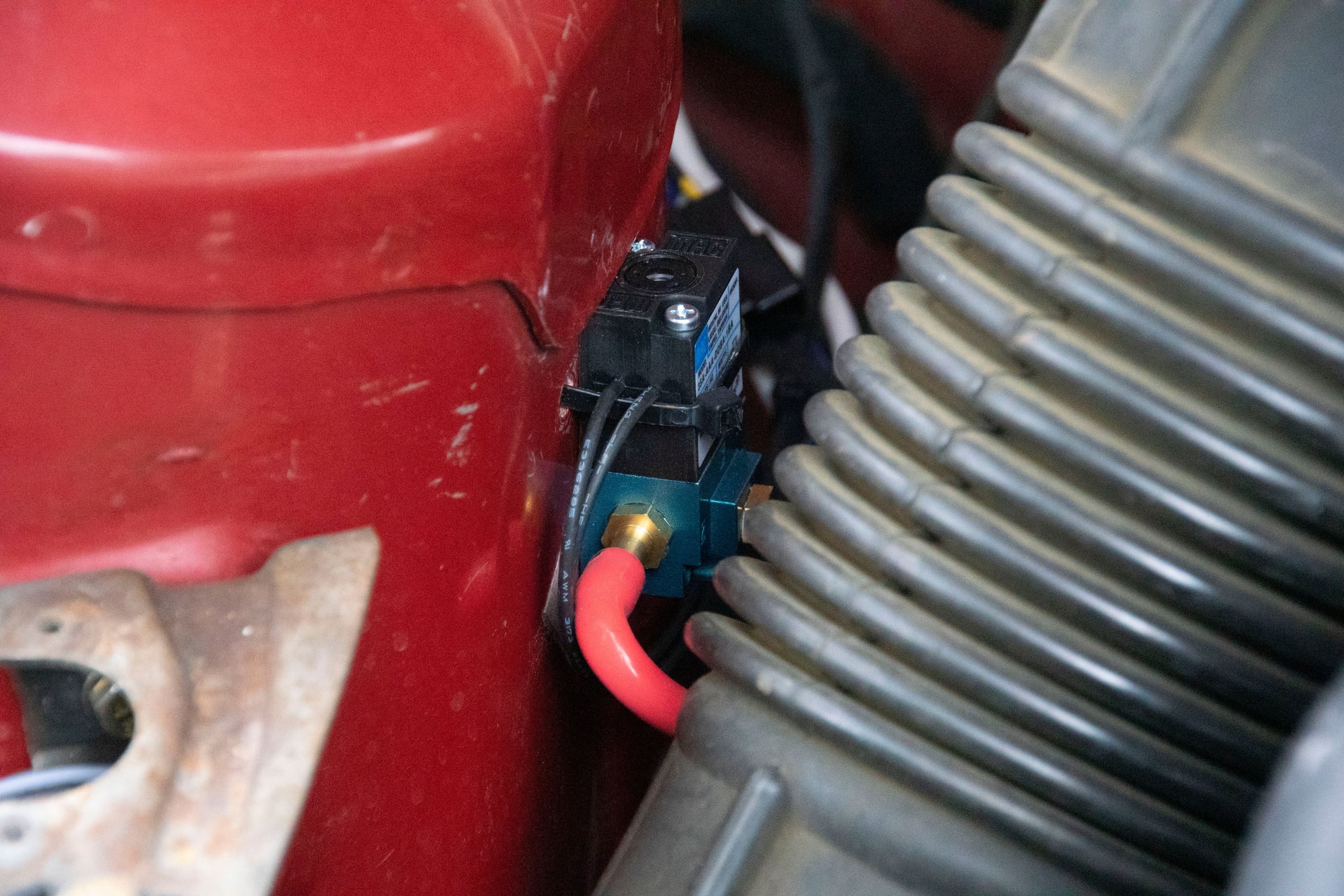
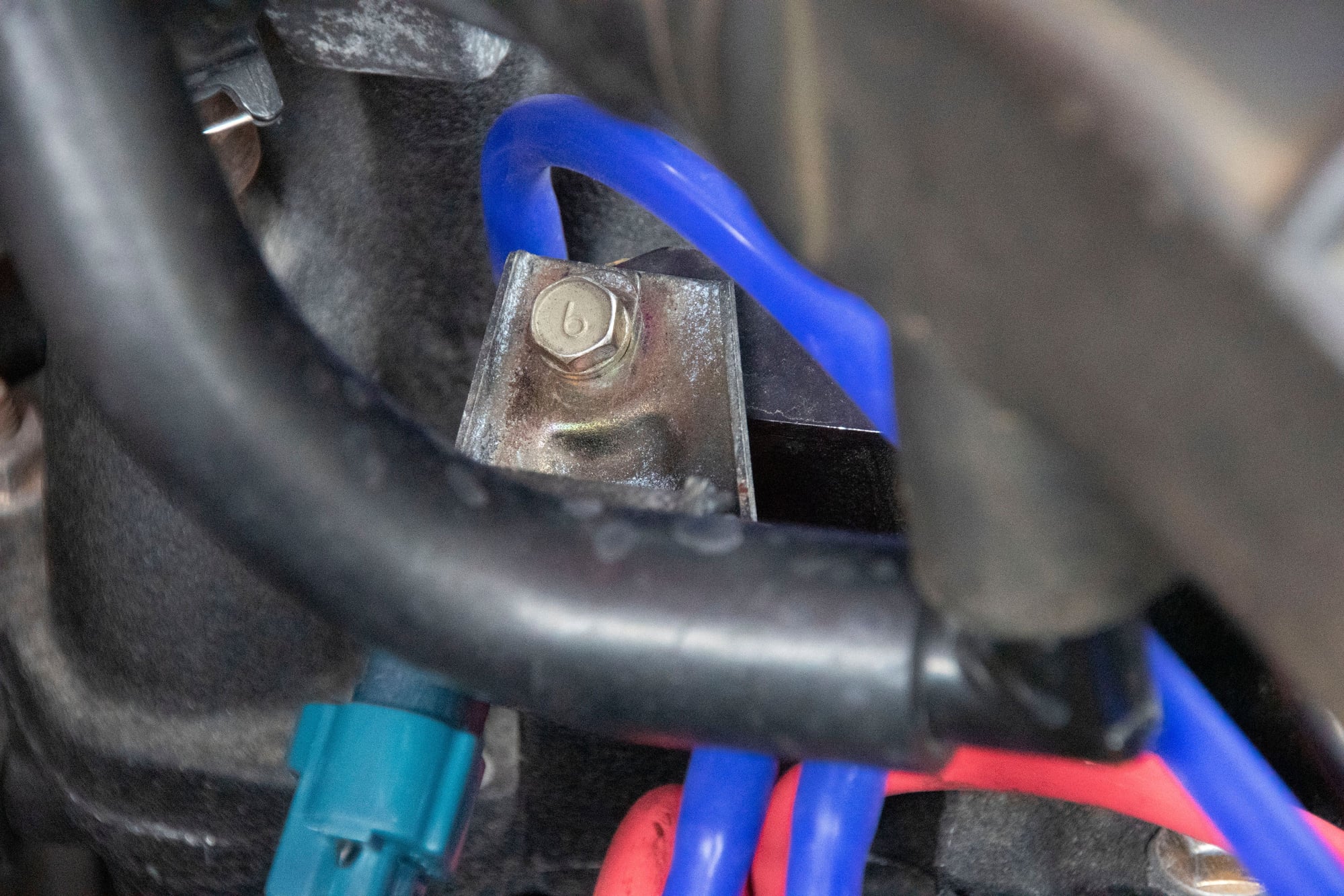
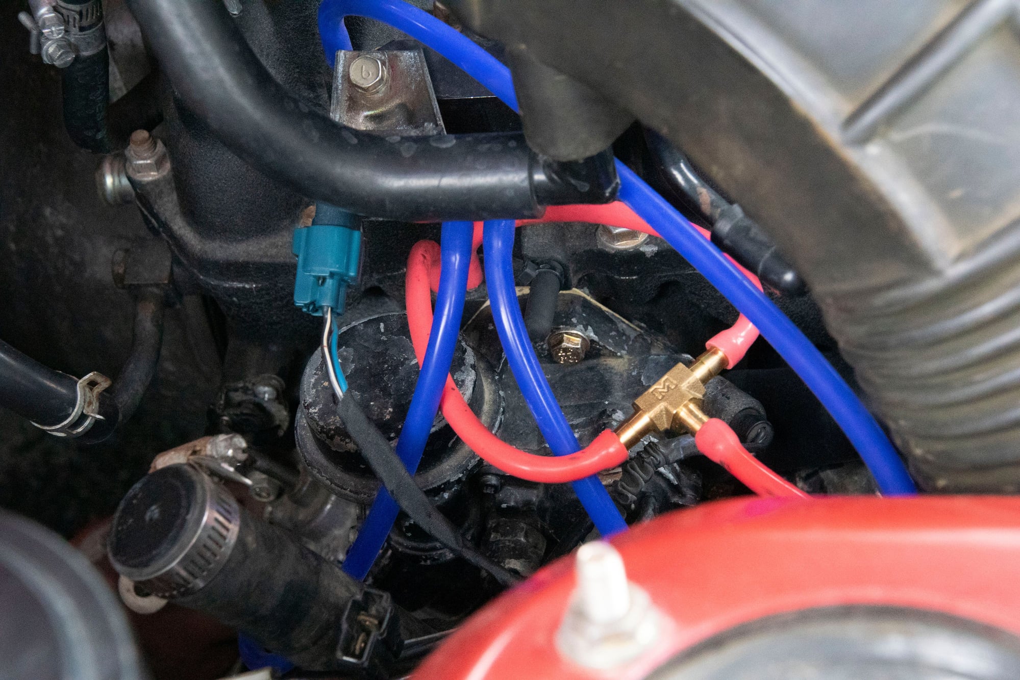
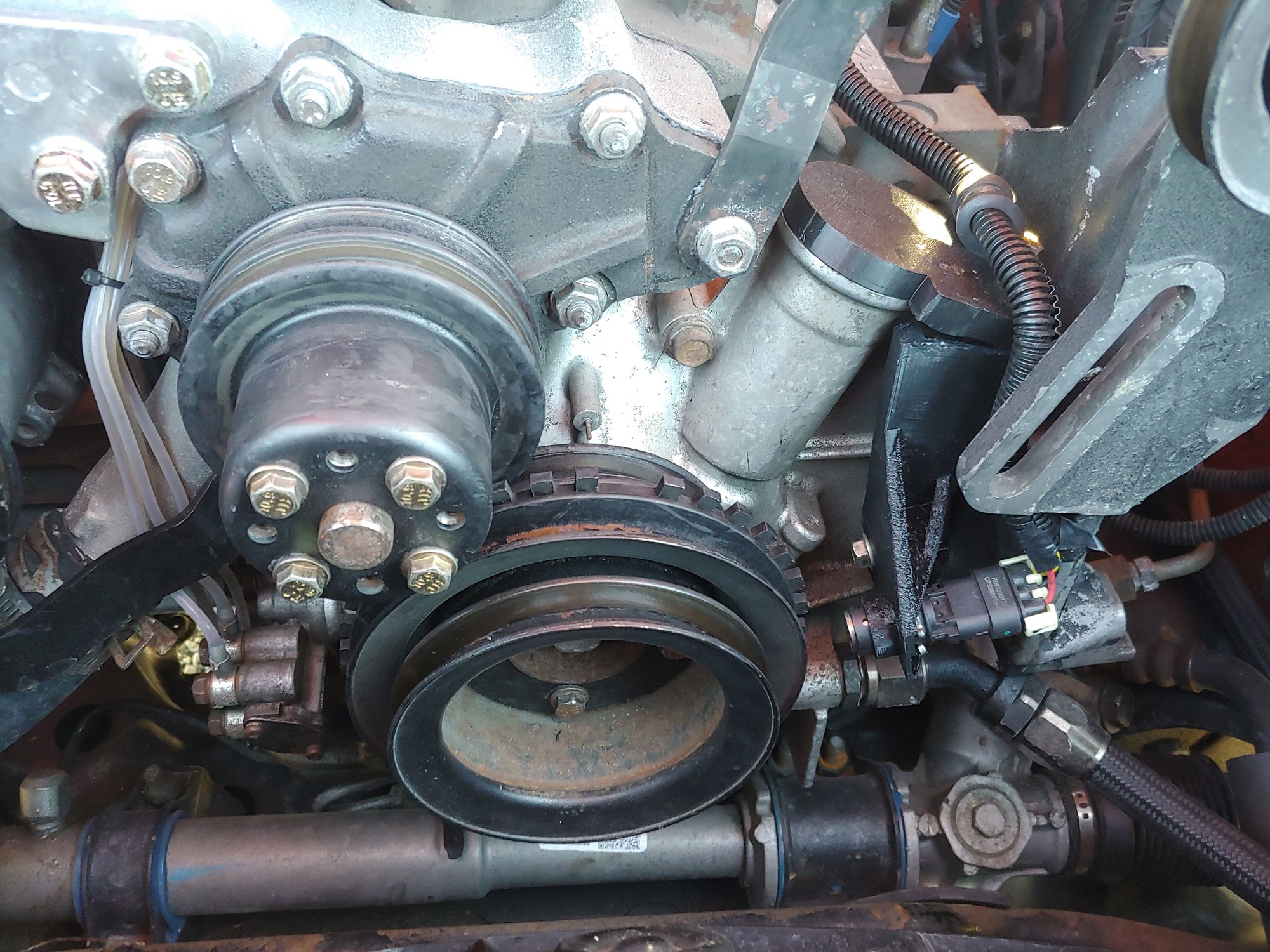
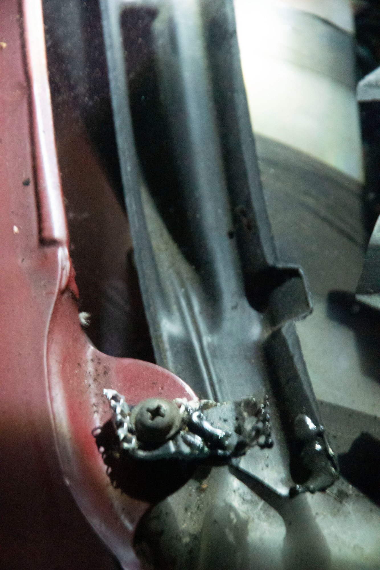
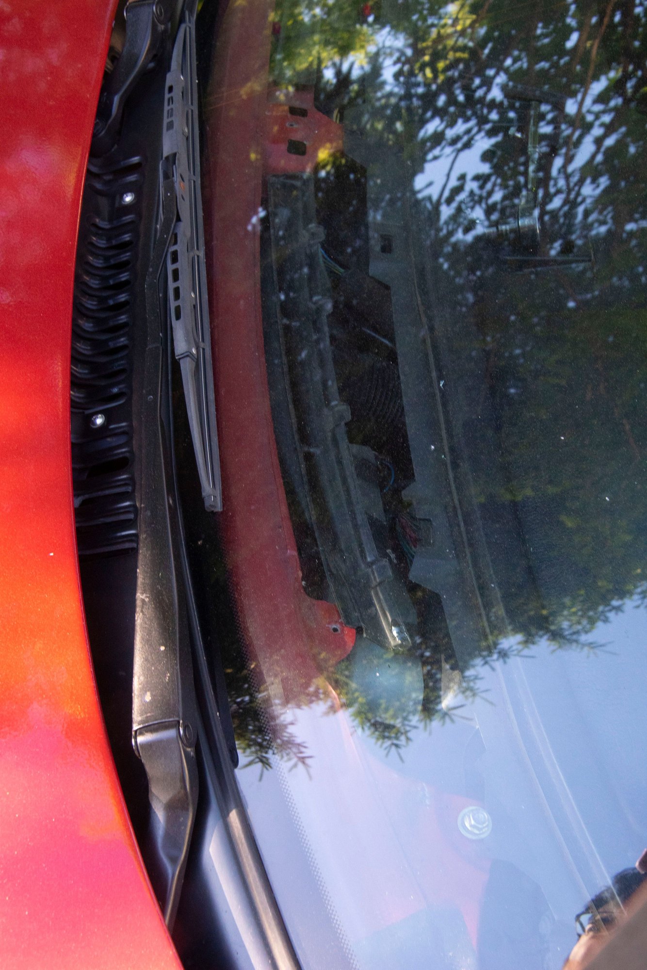
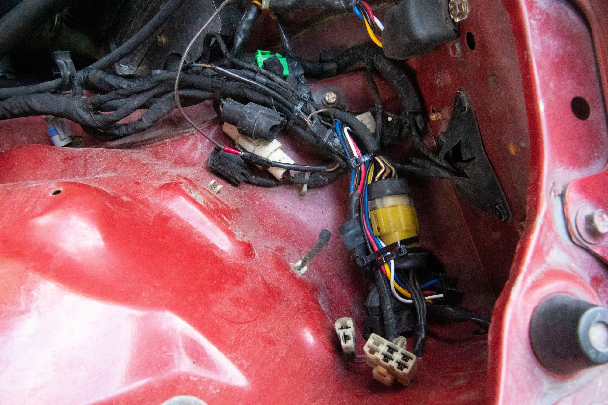
With that, everything gets bolted up and put into the car. The wiring was very simple, I just made a little sub-harness and ran it down to the ECU. +12V, signal ground, power ground, signal.

Then I needed to make the relevant ECU changes:


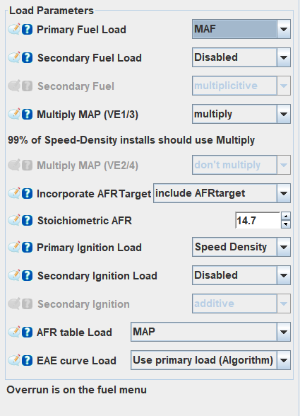
This might look confusing because I'm still using speed-density on it, but hear me out:

- Primary Fuel Load (the way the MS3X calculates how much fuel to inject at any given time) is changed to MAF. I'll discuss how this affects tuning shortly.

- Primary Ignition Load and AFR Table Load are still speed-density. This lets me use my old tables as-is, without having to rescale the y-axis. If I changed these to MAF then I would have to find out the relationship between manifold pressure and air flow and scale the y-axis appropriately for my old values to work. I should note that I DO intend to do this in the near future once everything else is 100% worked out. It's just that for now it was much easier to start with known good ignition timing and AFR values.

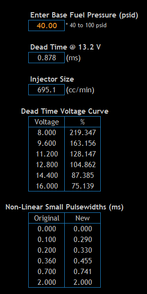
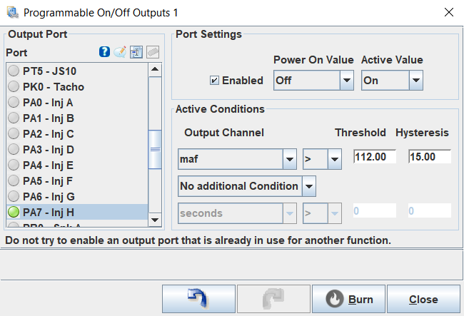
Then I had to set the MAF settings:


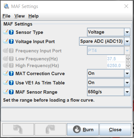
- The Z32 is a voltage type sensor. Many modern sensors are frequency type, so look into that if you are doing a similar conversion.

- MAT correction curve allows a percentage correction for the MAF based on the intake temp. This can be useful if your MAF becomes inaccurate with heat-soak, but wasn't necessary for me. While the setting is enabled I have that curve zeroed out.

- Use VE1 as trim table is a way to enable the VE table as a multiplicative correction on MAF. I'll explain what this does later, but again, it's enabled in my setup but I am not using it (table is set to 100 across the board).

I don't really know what sensor range does other than possibly affect the visual scale and initial values of the flow curve in settings. You need to manually input the flow curve values for your particular MAF anyways. I selected 650g/s because it was the closest to the values I found.

Speaking of values, I started with an "official" Nissan flow curve I found online. Turns out it was 100% wrong for my setup, needing to be leaned out by at least 25% just to run.

So as a quick refresher, let's talk briefly about how speed-density tuning works:


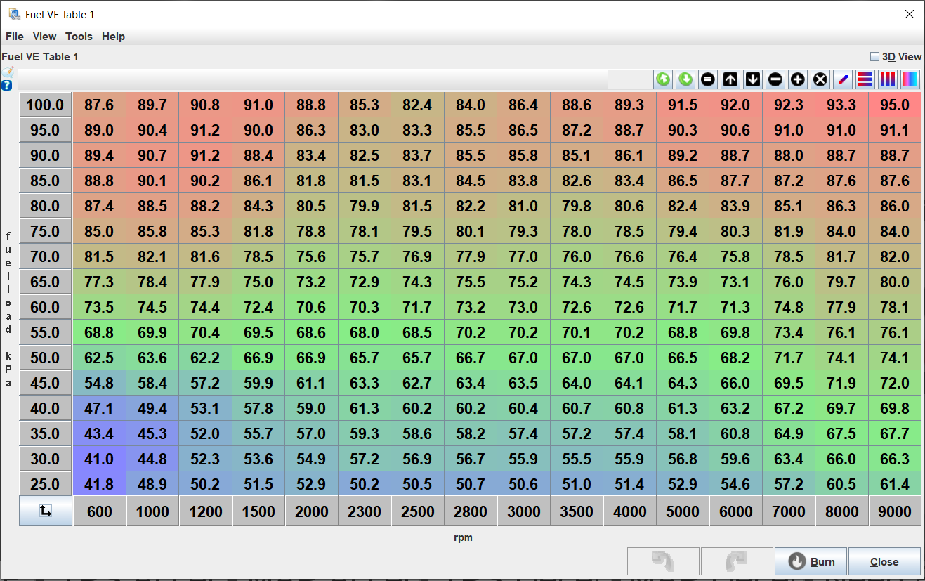
This is the VE table in a speed-density setup. You need to try and hit every bin and make sure the car is hitting your target AFR for said bin in open-loop:


So if target AFR at 3100 RPM and 50kPa is 15.2, you want to adjust the equivalent VE cell until the engine is running as close to 15.2 as possible. Tuning for a specific AFR isn't good practice since we actually want to do whatever makes the engine happiest rather than hit an arbitrary number, but assuming the AFR target is correct we can try to get as close as possible by adjusting the VE number. These tables really need to be tuned in tandem, finding the AFR that the engine wants at the same time as you find the VE that achieves this AFR, and then putting that target into the table for the closed-loop.

The complication is that there is no real "link" between those tables other than in closed-loop when the ECU is trimming fuel to try and hit the targets in the AFR table. The other thing is that high load + low rpm is not the same as high rpm + low load in terms of airflow in the VE setup, so you need to try and hit a bunch of awkward bins (go up a hill at 1500rpm in 4th with the pedal flat to hit the top left, or travel at 7000rpm with the throttle cracked open doing 40kph to tune the bottom right). It complicates things a lot without a dyno.

Then once the VE table is as close as we can get it, the closed-loop algo should take care of minor variances.

In comparison, here's what MAF tuning looks like:


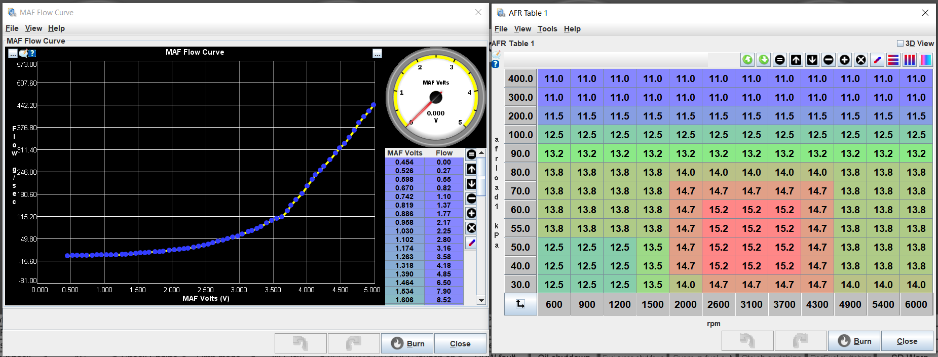
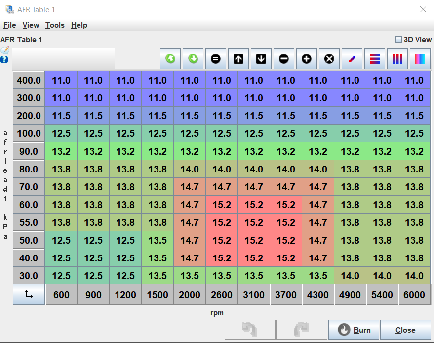
With MAF it's entirely different. Instead, I only use one curve and a table. The curve on the left represents the flow rate of the MAF (grams of air / sec) at a given voltage. The ECU doesn't have to take the VE number and do any math with the MAP, it just takes that number (say 1 gram) and then multiplies it by the target AFR for that bin. So at idle the ECU is just taking ~2.8g of air and using the air-fuel ratio to calculate how much fuel is required, then opening the injectors the appropriate amount.

The left axis still shows kPa in that AFR table, but the ECU isn't actually using it for any calculations. All the ECU is using MAP for is to know which AFR to target based on that table, and then otherwise the sensor is basically not used. This means that (assuming the flow curve is correctly calibrated) the AFR table itself dictates how much fuel is injected. If I want to idle at 13, even in open loop, I just drop 13 into the desired cells. Or 14, or 15, etc. I don't need to change the cell values in the VE table and then see what happens on the wideband and tune it in. It just works. If it doesn't, then either the calibration is wrong for that flow rate or there is a vacuum leak / other issue. The reason my curve is choppy above 3.7V is that I can't make it flow more with my current engine. That value is only ever hit when I'm in 4th gear going at a pretty good clip, and I would need to be going very fast to flow more air in an NA car. Turbo car should be able to do it under hard accel.

Closed-loop works the same as in the speed-density setup, it just doesn't need to do as much work.

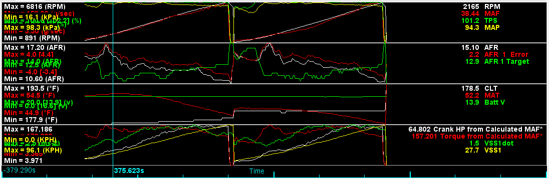
Now I mentioned before that I had to tune the entire flow curve myself because the ones I found online were way off. I didn't really go into how to do this yet. Take a look at this log:


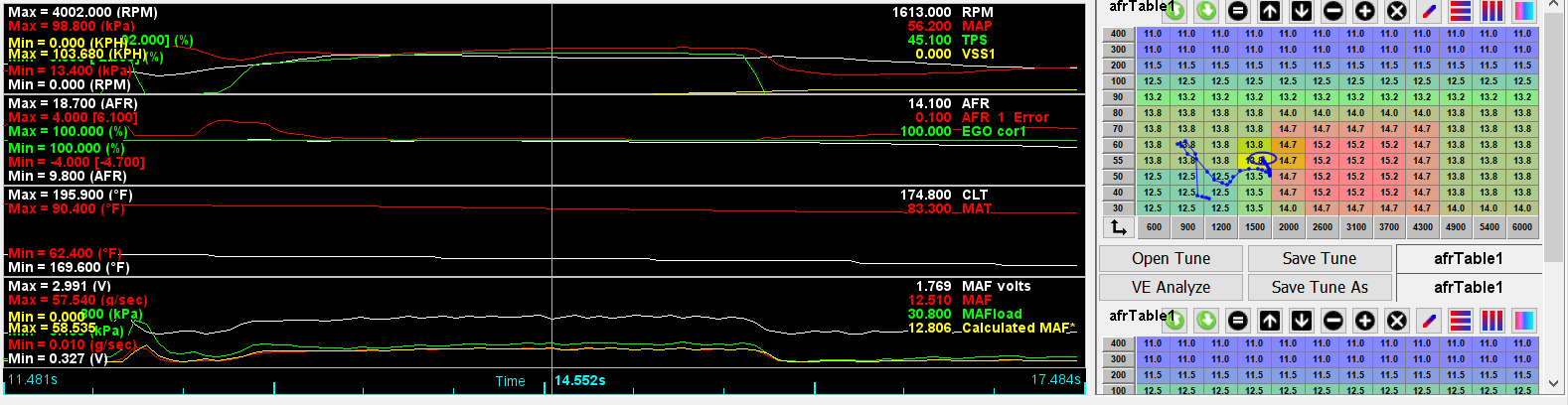
The right side shows the AFR table, but the important part is on the left. The second box from the top shows AFR and AFR error. So it's targeting 14.1 but it's 0.1 off of target. I can also see the MAF volts and flow at the bottom. So this part of the curve is pretty well tuned, but if not I would open TunerStudio and increase or decrease the g/sec value at 1.769V.

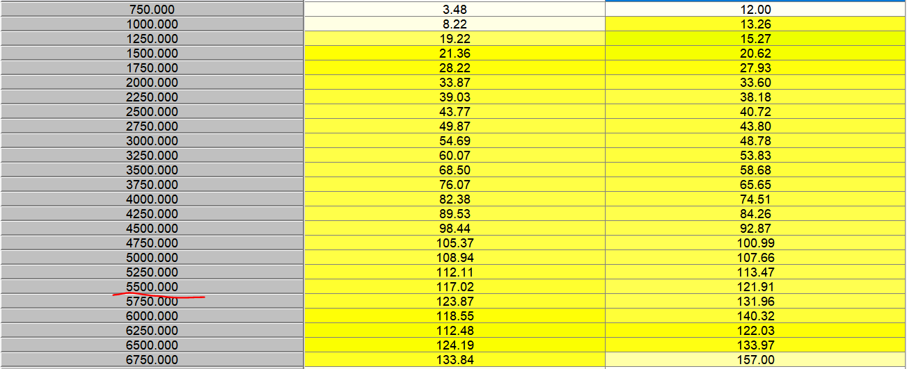
I also have an equation I made to do it for me which is why there's a "Calculated MAF" value. That's a custom field that takes the MAF g/sec reading (red line, 12.510 volts) and multiplies it by (Measured AFR / Target AFR) to make a "corrected" value I can drop into the curve at that point. Users on MSExtra were kind enough to offer some help and also show me that MLV has a histogram function that lets you define the scale:


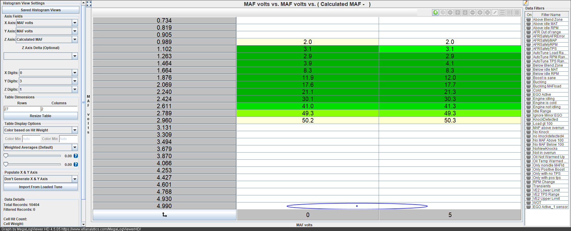
So basically the scale on the left has the same voltage units as my flow curve, and the histogram on the right shows the average of all Calculated MAF values. This means I don't need to hit an exact voltage value and hold it either, since MLV will do the job of fitting the values to this scale for me. I can just take a nice long drive and then copy / paste these values into the flow curve. The darker the green colour, the more "hits" at that voltage value during the drive and the more accurate the number is likely to be.

It's not a perfect system. I found it took several attemps because my equation will overshoot slightly. If it's targeting 13 AFR and measuring 12.5, and I take the Calculated MAF value for that and drop it in the curve, next run I'll measure 13.2 under similar conditions. Run it again and put in the new value, I'll get 12.9. It needs to be done again and again until the curve smooths itself out.

This would be a great opportunity for the Tunerstudio developers to create an autotune for it, but they haven't. The VE "correction" table can be autotuned, but that tends to result in some weirdness because it's still trying to use two independent variables (MAP and RPM) to calculate the correction value for something that only has one independent variable (airflow). So it doesn't seem to work very well when used that way, but then the developers didn't seem to intend it to do that in the first place.

And what's the result?

First off I have yet to re-enable closed-loop and the car is almost always within 0.3 of target AFR. Usually 0.1 at steady state conditions. It's super accurate even without correction, and I can probably get it even closer by tuning the curve more. Second, I need almost no acceleration enrichment or after-start enrichment. I also noticed it's much smoother returning from decel fuel cutoff, and throttle response is generally improved. The MAF reacts so quickly to the changes that the speed-density algorithm struggled with. Third, the tune doesn't drift with outside temperature anymore. I thought it did until I got the flow curve dialed in, and now it's rock solid all the time. I don't need the closed-loop algo to help with hot starts anymore.

The only thing I have yet to tune out is that it runs a little lean after warmup ends (at 176 degrees) for 5 minutes or so before running properly and hitting target AFR. Meanwhile if I'm driving the car on a cool day the coolant often drops below 180, so I can't keep the warmup enrichment on longer or it activates when already warmed up. Still haven't figured that one out yet. The closed-loop algo can probably handle this but I'd rather tune it out the proper way if I can.

Overall I'm really happy with how it turned out. It was a bit of an adjustment to how I had learned to tune, but the results were well worth it. Until next time :)

adam525i
adam525i GRM+ Memberand SuperDork
4/3/24 7:14 p.m.

Thanks for the detailed post, very interesting. I'm finding similar issues with my E28 running speed density, it's close and I'm happy with it but I know it could be better. There's also a set of ITB's in a big box in my storage shed that I won't run without a plenum which makes me wonder if a MAF would be a good way to go when I get around to playing with them. Measure the air mass going in, add fuel, simple.

rdcyclist
rdcyclist GRM+ Memberand HalfDork
4/4/24 3:01 p.m.

In reply to WondrousBread :

Excellent explanation of the tuning process! Thank you taking the time to write that up. It certainly gives us analog guys a better idea of how the digital process works. yes

WondrousBread
WondrousBread Reader
4/5/24 1:39 p.m.
adam525i said:

Thanks for the detailed post, very interesting. I'm finding similar issues with my E28 running speed density, it's close and I'm happy with it but I know it could be better. There's also a set of ITB's in a big box in my storage shed that I won't run without a plenum which makes me wonder if a MAF would be a good way to go when I get around to playing with them. Measure the air mass going in, add fuel, simple.

It really minimizes the amount of time spent on the compensation tables. My speed-density tune was good, it was just the little things that added up to make me want something better. I'd say give MAF a try (the Z32 MAF was <$100 and can always be resold if you don't like it). Once you wrap your head around the way they're tuned it's actually a lot simpler.

WondrousBread
WondrousBread Reader
4/5/24 1:42 p.m.
rdcyclist said:

In reply to WondrousBread :

Excellent explanation of the tuning process! Thank you taking the time to write that up. It certainly gives us analog guys a better idea of how the digital process works. yes

Thank you! I'm considering wrapping this all into a proper instructional post, or maybe a YouTube video, starting with the process of selecting a MAF (R35 is probably more ideal), designing the adapter, installing, wiring, and then the tuning. The number of people running MAFs with a standalone is comparatively small. It makes me wonder how many are happy with their speed-density tune and how many have just learned to tolerate minor hiccups.

Meanwhile I can never get a carburetor to do what I want for more than 15 minutes before it needs adjusting again :) I just can't seem to get the hang of them.

WondrousBread
WondrousBread Reader
4/5/24 1:42 p.m.

Oh, and I never actually mentioned why the R35 MAF is a better choice.

The R35 MAF is a newer hot-film style which allegedly reacts a bit faster than the hot-wire type. I don't know if this matters, but theoretically it might provide quicker reactions to throttle input and require fewer compensations (not that the Z32 MAF isn't fast already). It also includes an IAT sensor built-in which is really nice from a packaging standpoint, and has a simple two screw flange that lets it bolt into any number of available housings. If available housings don't work for a given setup, the simple flange will also make it easy to design a custom housing and have it printed. Or buy a flange in aluminum, locate it where you want it on an aluminum tube, and have it welded in.

Add to this the natural advantages of the R35 MAF from a non-technical standpoint (it's newer, similarly priced, they seem to be more plentiful, there are aftermarket versions, etc) and it just makes more sense. The Z32 MAF might be more convenient if they were common or fit without an adapter, but then I needed the air straightener anyways so it is kind of a moot point.

DarkMonohue
DarkMonohue GRM+ Memberand Dork
4/7/24 9:58 p.m.
WondrousBread said:

The number of people running MAFs with a standalone is comparatively small. It makes me wonder how many are happy with their speed-density tune and how many have just learned to tolerate minor hiccups.

There's probably a natural aversion to adding anything that doesn't strictly have to be there - the "you don't need that" philosophy you mentioned earlier. Then you have the additional cost, the tuning and wiring complexity, the fact that the part sits right in the intake tract and could be viewed as a potential restriction to airflow. Still, OEMs meter airflow for a reason...

You're doing a really nice job documenting your work on this car. I'd much rather follow along with something relatable like this than watch someone fire the parts cannon at some monster build. Keep it up!

WondrousBread
WondrousBread Reader
4/8/24 7:41 p.m.
DarkMonohue said:

There's probably a natural aversion to adding anything that doesn't strictly have to be there - the "you don't need that" philosophy you mentioned earlier. Then you have the additional cost, the tuning and wiring complexity, the fact that the part sits right in the intake tract and could be viewed as a potential restriction to airflow. Still, OEMs meter airflow for a reason...

You're doing a really nice job documenting your work on this car. I'd much rather follow along with something relatable like this than watch someone fire the parts cannon at some monster build. Keep it up!

Thank you for your kind words! Maybe one day I'll fire the parts cannon at it, but for now my goal is to just have a nice driving car that's reliable enough to enjoy.

One interesting opinion I've heard is that the OEMs only meter airflow because they want to maximize fuel-efficiency. But to me that seems like a compelling argument in favour of the MAF. It also seems to me that for those of us tuning the cars ourselves, especially with limited or no dyno time, it's worthwhile to have every advantage possible working in our favour.

WondrousBread
WondrousBread Reader
4/16/24 8:11 p.m.

The trigger wheel arrived, and at first glance it looked pretty good:


But when I actually placed it against the pulley, it wouldn't sit flat. Turns out it's significantly warped:


It would be fixable, but I'd really rather start with a part that is straight. PCBWay has pretty good customer service so I don't anticipate any issues getting a replacement. It does push the timeline out a couple weeks unfortunately.

WondrousBread
WondrousBread Reader
4/20/24 6:52 p.m.

When I restored the air pump, the main goal was to restore proper aux port actuation. I also said I thought there would be a way to gain some area under the curve. This is the post where that all comes together (sort of).

The first thing I needed to do was add in some solenoids, and connect them to my MS3X through a sub-harness. There's one MAC valve on the shock tower:


One stock S5 boost solenoid (borrowed from my Turbo II engine) on the manifold, where the sub-zero cold start assist system used to live (obscured by this hose I probably should've removed for the sake of the photograph):


And a big mess o' vacuum hoses:


So what is going on here? I'll explain:

- One source of vacuum (uppermost blue hose) runs to the MAC valve inlet. Then from the MAC valve outlet, that vacuum is split to the two nipples above the ACV.

- The nipple I added to the air pump outlet connects to the S5 boost solenoid inlet, and the outlet of the solenoid connects to the aux port air supply tube. There's a small hole in the hose on the aux port side to allow air to flow back when the ports return to their home position, otherwise they can get stuck open.

This should in effect give me complete software control of the ACV, but also (in theory) allow for continuous control of the Aux ports rather than the discrete on/off behaviour of the stock system (since I can control the pressure at the outlet by varying the duty cycle on the solenoid). Now, the last part really didn't pan out and I'll explain why in a minute. But it's worth talking about how the stock system works before I move on to my findings.

In the stock system, puttering around at low rpm / low load the ports remain closed. Once you reach a certain amount of load (the training manual says "4500 rpm" although it is in-fact a load based system, not rpm) the ports open and you get the additional intake timing. The way the manual specifies an engine speed is a bit incomplete (6000 rpm at 10% throttle probably won't cause enough back-pressure to open the ports, but 4000 rpm at 100% throttle might).

Now when I say that they only have a discrete "on/off" behaviour I don't mean that in the literal sense - the manual lists 1.2 psi as the point where the actuator should start to move, and 2.1 psi as the point where it's done). But in my testing the actuators have basically three positions: "Closed", "Open slowly", and "Open quickly". I can't find any duty-cycle that causes the actuators to hang at 1/2 way for example. So while I can smooth the transition a bit by setting say 50% duty, I can't actually hold a specified intake timing. At least with my current setup.

So with that knowledge I decided it was time to try and find the best transition point for the ports. I started by setting the duty on that solenoid to 0, and then started a second gear run from idle to redline. Then I changed the duty on the solenoid to 100, and did an identical run. Once I got home I cut out the remainder of the log to end up with the following:


You can kind of see the trend there, but it isn't very clear because there's a lot of other things going on. Conveniently the histogram tool in MLV makes it easy to cut out the noise and visualize the data, and also lets me specify the y-axis units:


If that still seems confusing then here's what's going on:

- The left hand side shows the engine RPM.

- The middle column shows the MAF reading at a given RPM value with the Aux ports closed.

- The right hand side shows the MAF reading at a given RPM value with the Aux ports open.

Most of the alternative Aux pump actuation methods I've seen either just tap off the air pump (tying the aux port actuation to engine speed, although the exact RPM at which it changes over is unclear), or sometimes use an RPM based switch to allow the user to select the engine-speed for the changeover. Either of these works fine, but from experience the Aux ports being open too early (say 2000 - 2500 rpm) is noticeable when driving.

So I really wanted to be a bit more scientific about it. The rationale for the aux port is that at low load the smaller secondary ports are more efficient. In my (admittedly amateur) understanding of the engineering concepts behind this, this is because a port being too large causes a decrease in flow. I'm assuming that (like an exhaust system with too great a diameter) this is due to the turbulence in the large port causing a decrease in overall flow. The aux ports only become efficient at high load because at that point we are exceeding the limitations of the primary + secondary ports in terms of flow.

With that in mind, my intuition is that MAF is actually the best measure of where to configure the changeover (since we want to pick the point where we are outflowing the primaries + secondaries, not some rpm value). Someone running speed-density could use the calculated air flow as a proxy and it would work just as well. We don't actually care about the number so much as the comparison, since the MAF flow curve was not changed between those two runs and we know it will be consistent. So with all of this in mind, here's a PowerBI graph visualizing the above data:


There are a couple of really interesting things about it (keeping in mind that both of the above runs are at WOT so throttle doesn't enter the equation here and we can speak in terms of rpm):

- There is surprisingly little difference from 1500 to 2000 rpm. This might just be due to the poor low rpm chamber filling of the rotary engine itself, but that's just me speculating.

- There is a surprisingly large difference from 2500 to 4500 rpm. This is definitely noticeable when driving. At 3500 rpm it's around 15% more flow with the ports closed.

- The aux ports only become efficient at 5200 rpm. About 1200 higher than the commonly accepted online 4000 rpm number for when the ports are "supposed" to open, and still 700 rpm higher than the training manual's 4500 rpm figure.

- Something's going on to cause that dip at 6250. I think it's tune related. My AFR table still references map for the load which might be causing some weirdness (MAP by 6000rpm shows as 90, which is actually less than the 95-98 I see earlier in the run), and I also noticed AFRs started to get really rich nearer to 7000. In fact, AFR was actually out from target quite a bit during this entire run, so I'll need to revisit my flow curve to see what's up.

Now there are some mitigating factors. For one, I only did one test run. A proper test would involve many back-to-back tests. Two, my car is not stock. The engine itself should be a stock port S4, but I have a different MAF from factory and my exhaust is probably flowing more than stock with it's 3" diameter from the catalyst back. It's not clear to me whether the behaviour I observed would be the same for a stock car (although admittedly I would've expected a modified car to outflow the primaries earlier, but then air flow is a complicated thing). And lastly the intake temp drops a few degrees between runs.

But this does tell me where to configure the changeover:


The reason I picked 112 g/sec and not 118 (where the lines cross in the graph) is that it takes a moment for the ports to open. So I want the ports to start opening slightly in advance of then. The hysteresis value was just something I picked somewhat arbitrarily to prevent the solenoid bouncing around. I'll only know whether 15 is a good number with testing.

So for now that's where I'll leave it. As soon as I get the chance I'll do another back to back to back test with the ports always open, always closed, and opening at my configured set point. Then I can overlay the three lines and see what happens. Until next time :)

WondrousBread
WondrousBread Reader
5/13/24 7:51 p.m.

I have an update, albeit sort of a frustrating one. I was able to weld up the gear from PCBWay with no issues:


There was no drama. I clamped it firmly and welded in a few places, and the warped trigger wheel straightened out reasonably well. It could be a bit straighter but I don't think it'll be an issue in real life. Unlike VR sensors, hall sensors are quite forgiving.

I also sorted out some 3D printer maintenance and was able to print this bracket. It's in PETG (PC is stiffer but is finicky to print, so PETG is what I'm using for all the prototypes). If I grasp it firmly at the sensor end and push I can still flex it, but I think in application the amount of flex will actually be very minimal. Especially since there's no force on it front to back in real life.

I bolted it up (well, zip-tied) on the Turbo II engine to test, and everything looks pretty good:


Clearance to the trigger wheel looks good.


All the pulleys still clear.


Another view of the PS idler pulley still clearing the bracket even at it's lowest adjustment.


Clears the water pump pulley snout.


Clears the water pump pulley face.

So overall everything has gone really well. Except for the minor snag that it doesn't fit my S4 engine currently in the car, so I can't actually test it. It turns out the S4 water pump snout is different and so is it's pulley. The bolt holes line up but the centering bore is different. The actual snout is also in a different place relative to the water pump housing, so it's a bit closer to the crank and my pulley won't bolt up.

In my defense, the water pumps look nearly identical. I think it's only a few millimeters difference. But it is enough that I can't actually test. So for now I'm driving around with a prototype (using my old trigger wheel), but I can't actually test the new design until I swap engines.

Also I had a couple posts over on Rx7Club that go into it further, but there seems to be no duty cycle that allows me to hold the AUX ports open at a point between open and full. They either don't open or open all the way. I can think of a few ways to solve this; electric air pump so the pressure isn't tied to RPM, solenoids with bicycle cables, and I even drew a simple design for a fully mechanical linkage system. But overall it doesn't really warrant the expense or effort at this point since I want to swap engines anyways. It drives great so for now it will stay as-is.

I should have another update in a few days which you guys might find interesting. Until next time :)

WondrousBread
WondrousBread Reader
5/21/24 7:17 p.m.

Alright folks, it's storytime.

Today I hopped in my Rx7 after work for a brief trip to the nearest Purolator drop-off. I drove all the way there without incident, until the moment when I was about to enter the parking lot. Suddenly the tach went a little crazy and then the car just died with a weird clatter noise. It was still rolling (sort of) so I jumped out and pushed it the rest of the way into the lot and parked it. I managed to run over my own foot while doing so (but the Rx7 is light so it turns out that's no big deal).

I had expected a number of things. Maybe my bracket had come loose, or deformed from the heat. It was none of what I expected:


Remember the crusty old air pump belt that I was using? The one that I found on my shelf and came with the car 8 years ago? The one probably older than me?

Well, I let that temporary belt become permanent and I got what I deserved. The belt snapped, took out the alternator belt with it, and then snapped my bracket nearly clear in two. Here's a picture of it once it was removed:


Now as luck would have it, there was another bracket hot off the 3D printer and my dad was kind enough to bring it to me. I also grabbed a mostly correct alternator belt from the Canadian Tire, and the kind people of Staples (where I used to work) let me use their tools to remove all the support structure from the bracket.


The 3D printer really mangled the edge of that gusset, but that's a problem for another day. Met some nice strangers in the parking lot and we talked cars for a bit before I set off. I was able to get home without incident and the car will be laid up for a couple of days while I order the correct belts, and probably go back to my old sensor in the air pump location temporarily so I can drive the car without fear of this happening again (unlikely though it may be).

I learned something important. I definitely want to get the final bracket either printed in aluminum or CNC'd. A snapped belt is irritating, but if I hadn't had a bracket on the printer and my dad available to drive it over I would have been 100% stuck in that parking lot.

Overall though, I'm home and the car is fine. Plus I learned something and got to fix a problem on the fly. Not a bad way to end the day.

WondrousBread
WondrousBread Reader
6/15/24 11:51 a.m.

I had time to take care of a couple of small interior things that have been irking me, so I took some pictures along the way.

First off, my cigarette lighter socket stopped working awhile back. Confusingly enough I could actually see 12V on the multimeter when probing it, but then my USB adapter wouldn't light up. I decided the only thing to do was to take it apart and see what was going on:


So, this is kind of weird. If you look at the center piece in this image, that's the part that connects to the harness connector that provides 12V. Then the contact that sits inside the socket conducts through that center screw.

If you look carefully at the center piece you'll see that it's actually two pieces with a washer between them, and for some reason this washer is a non-conductive material. Then there's a small jumper wire that actually conducts the electricity.

This is kind of a weird choice. It's like one engineer decided to use a non-conductive washer and another one decided to use a jumper wire, and they never spoke to one another. I thought the small wire might act like a fuse, but this circuit is already fused so why put it there? I ended up replacing the little wire and that fixed the connection.

While I was at it, I also noticed an issue with the little light channel that throws light at the ring around the socket:


It's crooked. Probably because it's held on with JB Weld and I got it a bit crooked last time, but this is unacceptable. The socket lights up perfectly but the little outlet for the ashtray is misaligned. This means the light in the ashtray is dim.

Entirely unacceptable. How am I supposed to observe my ash collection in the dark?


With the new wire (and a lot more JB Weld) I had the socket issue fixed. Now I just need to start smoking...

I also wanted to take care of one place on my car where the interior dye didn't really hold up. This is the glove compartment lever:


It looked great when I first did it, but it's a high-traffic part and it's showing wear. Plus the bubbles indicate poor surface prep. Plus I was able to scrape a lot of that paint away with my nail.

I stripped it all back and sanded with 1000 grit sandpaper to break the shine, then degreased it thoroughly:


And hit it with SEM Color Coat:


The SEM is definitely better than the Duplicolor. I originally picked the Duplicolor purely because I like the satin finish better, but I'm a low-maintenance kind of guy, so if/when I have the occasion to take the interior out I'll strip it and recoat with the SEM piece-by-piece. That's assuming it stands up to regular use of course, since the glovebox lever will always be a high-traffic surface.

Next up is a choice that people might find a bit odd, but I installed a CD changer. I've had the matching Nakamichi MB-9 changer for my head unit for several years, and I actually wired the car up for it before deciding not to install it. Between the Minidisc deck (I have plenty of blank Minidiscs and a deck in my room to write to them) and the auxiliary input I thought that would be enough, but it isn't.

A Minidisc holds about the same runtime as a CD, which means every 80 minutes (assuming you don't skip any songs and don't feel like listening to something else). That's actually not a very long time. The same problem occurs with the auxiliary port because it tempts me to pick up my phone and change the song. Aside from being distracting, that's a serious offense here in Ontario and results in points on your license. My stereo obviously has no provisions for a Bluetooth connection nor do I actually want one. The last place I want to be easily reachable by cell is when driving my Rx7.

Also I like the spontaneity of the CD drive. Pretty frequently I like stopping by a garage sale and buying random CDs. For $10 you can get 10 albums and listen to something new. It's not like I find many Minidiscs at garage sales.

So whether or not it makes any objective sense in 2024 I decided to plug in the MB-7 and put it behind the seat:


The weird scratches on the front are from several years ago. I gambled on an "untested" unit on eBay for cheap (FYI "untested" on eBay means "I tested it and it's broken so I'll just sell it as untested") and it works, but something in the mechanism that lifts the tray doesn't work. So my solution at the time was to notch the front of the case under that door to allow it to just pop the tray out anyways. It's pretty ugly under there, but my work is (mostly) hidden when the door is on. That's not the solution I would choose if I were doing it today, but I must have felt differently when I was 18.

This unit is pretty neat though. The head unit can control it seamlessly without the need of an external remote, and it has both analog outputs and a coax digital. I'm sure the analog would be good, but my head unit accepts a coax in so I went with that. I figure that Nakamichi probably put it there with the idea that the DAC in the head unit is superior anyways.

The other benefit is that the Minidiscs rattle around in the door pocket. You can fit more of them, but it's also tough to see which is which:


Whereas CDs fit perfectly, and unlike my home dubbed Minidiscs they all have album art:


The Minidiscs now rattle around my center console instead of rattling around the door. I'll probably whip-up a little custom storage tray for them that fits inside the console.

When I have time one day maybe I'll decode the Nakamichi changer control protocol and build a Bluetooth interface to let me use the controls on the head-unit to control my phone. I'll also need to make sure this solution doesn't play call audio (ideally it won't even interrupt the song), but then realistically I barely have time as it is so this project is a long way away.

But until then I can listen to CDs:


While smoking a cigarette:


And quietly observing my ash collection:

WondrousBread
WondrousBread Reader
6/15/24 9:40 p.m.

I've had a brand new OEM defroster vent sitting in a box for a few months, and for some reason I decided that now (after the weather has warmed up enough that I rarely need the defroster) was the time to install it. My old one had a crack straight across it's single mounting screw which I had unsuccessfully attempted to repair awhile back. Here's a picture of the new part:


Interestingly this part might actually be new:


I ordered in April, so that definitely isn't the date I ordered it. Unless maybe it's a batch number of some sort.

Here's a close up I took (at night, of course) of the broken vent:


And a nicer photo this morning that illustrates the problem:


As you can see, the broken fastener lets the vent fall backward of where it should and also sit a little bit lower. This means the hot air shoots up into the bottom of the dash garnish instead of out onto the windshield, hampering it's effectiveness. A repair might have been possible but when a new part is $25 it's hard to argue.

I also found this bolt was loose:


It was probably tight when I installed it, but the dash itself is cracked in that area so if it slides away from the windshield just a bit then tension on the bolt is gone and it loosens. I'd been hearing an occasional rattle deep in the dash someplace, and this is probably the culprit. On reassembly I used a big fender washer to try and grip what remains of the dashboard more firmly. Time will tell whether that works or not.

With all the dust and grime cleaned up and the new vent installed, you can see it sits quite a bit further forward:


For anyone interested, you absolutely CAN install this part without tearing apart the dash any further than I have photographed so far. You merely need to remove the single screw, unhook the inner fastener from the firewall structure, loosen the round inlet tube on the bottom, and then pull the vent up against the windshield and sort of rotate it towards you. You need to flex the vent a little bit but it won't break.

Unfortunately for me, when I was trying to remove the original vent I got it wedged in a weird position and convinced myself I needed the dash to come back a bit so I would gain more clearance. So I removed all of the dash fasteners and dropped my steering column to try and get myself the clearance I thought I needed:


... anyways, all I cost myself was about an hour's time. Plus I got to clean out some of the vents while I was in there. Remind me to design some sort of solution to install a cabin air filter.

Before I reinstalled the vent garnish I put some fresh foam on it to prevent rattling:


Once it's back in we can see just how much better the vent is aligned:


With the broken vent it was mostly under the garnish. I think this will greatly improve the effectiveness of my defroster, which I've always felt was a bit lacking. I'm also thinking a new blower motor would help, and so would resealing all of the vents under the dash with fresh foam.

Lastly I took care of a small problem that's been bothering me. With my relocated coolant reservoir, I would routinely lose a bit of coolant to evaporation. This didn't bother me a ton (it happened with the original reservoir too) but what did bother me was that liquid coolant would drip on the floor. In addition to a whiff of coolant smell every so often, and the green stains, I would always wonder "Is that dripping just the reservoir or have I actually sprung a leak this time?". Plus it's not good for the environment. While I wouldn't call myself an environmentalist or anything, I think it's a good idea to avoid wantonly damaging the environment whenever possible.

I figured the issue was that the original location (way over on the driver's fender near the shock tower) gave the coolant more time to cool down before reaching the reservoir. This made it less likely for it to evaporate.

The location where I installed my new reservoir is at the back of the engine bay near the highest point and also on the exhaust side. I had tried using a rubber cap with a small hole in it on the vent nipple for the reservoir, and also no cap at all, and either way the steam would escape and condense back into a liquid before dripping down. Turns out the solution was quite simple:


All I did was add this upturned hose. The hose adds a bunch of surface area on which the steam can condense, and then it drips back down into the reservoir rather than out onto the ground. Multiple drives later I have never felt any moisture at the exit of the hose. I'm sure I'll still lose coolant to evaporation, but at least it's minimized.

Also, my CD changer has already stopped working. It still responds to commands but no audio come out. I'm going to try diagnosing when I have time, but such is the life with 30 year old electronics.

Until next time :)

WondrousBread
WondrousBread Reader
6/29/24 9:20 p.m.

For awhile I've been planning on a fuel system upgrade. I'm obviously not maxing out my stock NA 460CC x4 fuel system or anything, but newer injectors have a number of benefits including:

- Higher flow
- Improved spray pattern
- Known injector characteristics (dead-time, small pulsewidths correction, etc)

To be clear, my goal with this is to eliminate some of the guesswork from my current tune (particularly injector dead time) and hopefully gain some fuel economy and idle quality. Larger injectors don't make more power, and generally larger injectors are harder to control at low pulse-widths which makes idle worse. But modern injectors also benefit from some significant gains in atomization, and since most of my injector characteristics for the stock units are educated guesses I am hoping that the gains will outweigh the losses.

Injector Dynamics was the obvious choice, and everyone says their products are second to none. The only problem is that their smallest injector, the ID725, is discontinued. I really didn't want to step up to the 1050 as that would be a lot more fuel than I need (even once the Turbo II engine is swapped).

So imagine how pleased I was to pick up an open-box new set from eBay for a very reasonable price. Here they are next to a stock Bosch injector:


The only problem is that they won't fit.

Obviously they're shorter than stock. This is intentional, and they are supposed to be run with the correct size of adapter hat for the application. But what I mean is that the top of the injector is actually shaped differently. Here's a stock picture I found:


See? The plastic near the top continues higher, and there is a small edge for the clip on the hats to engage with.

Turns out the reason the injectors I purchased were so cheap was that they were machined for a specific application. They were listed for Yamaha SHO, which I think is an outboard boat motor? I contacted Injector Dynamics and they were very helpful, but basically told me that there was no adapter to do what I was looking for and that the best solution is to just replace the injectors.

I did find some solutions that might work (I bought some 10mm to 14mm spacers from Aeroflow, and then the standard 14mm to 10mm top hats may have worked) but I wanted a solution that was secure. Also, some of the cheaper adapters don't include the strainer for the fuel, which I find sloppy.

We live in a time where we can make anything we want, so I spent some time designing this:


This adapter has the correctly sized inlet for my ID725s and outlet for the fuel rail, as well as a 6mm receptacle for the strainer and a small lip to prevent it falling into the injector.

I had a set printed in aluminum from PCBWay (only $34 for 5 units, and I already had store credit), and then tapped the strainer into place:


I also purchased a set of 4 Denso rebuild kits, so I had some fresh o-rings and donuts for the bottoms of the injectors. Here's how it all goes together:


The two o-rings on the injector are just for safety. I'm sure one would be fine, but o-rings are cheap. I also tested with those o-rings by soaking them in gasoline for a day. They're supposed to be Viton but you can't be too careful.

Here's a comparison:


And all four assembled:


The stock injectors use the rectangular Bosch EV1 connector, meanwhile the IDs use USCAR. I didn't want to cut my stock harness so I purchased these convenient little adapters:


To be continued

WondrousBread
WondrousBread Reader
6/29/24 9:21 p.m.

The next step was to actually install the injectors. I won't show the disassembly of the intake manifolds for access, since I've covered it before. One thing I will say is that eliminating the coolant running through the intake manifold makes the removal process much easier. I think it was maybe 10 minutes to have the upper / middle manifolds removed?

Here are the injectors I pulled out:


A few weeks ago I got in the car and turned on the wipers, and noticed that the wiper blades had lost their flexibility and weren't wiping very well. I thought "come on, I replaced these when I got the car!".

Then I remembered that I "just" bought the car 8 years ago. Time flies.

I had a similar experience with these injectors. Most of the ugliness is cosmetic (you'll notice the upper o-ring and the donut are in good shape still). I had these cleaned and flow-tested after I purchased the car and to my knowledge they are perfectly fine. But they are also probably one of the few original parts on the car which means they have 397,000 km on them. Does anyone know if injectors wear out?

Anyhow, I installed the ID725s. The install went without any drama, and the only thing I had to do differently was rotate the rear primary injector to put the connector on the inner side so it clears the oil injection nozzle. Without the EV1 -> USCAR adapter it would probably have fit fine in the original orientation.


It's kind of hard to see in that photo, so here's a photo of the secondaries:


I got the adapter height right on the first try. They fit very snugly with no wobbling, but also rotate smoothly with some effort.

Since these injectors are high-impedance, I needed to deal with the stock resistor pack. This is only required for low-impedance injectors like the stock ones. It's this big box that sits on the inner passenger fender:


There are 5 wires going into this connector. One central wire with 12V on it when key is in the IGN position, and then four wires that run through the resistor pack and to the injectors.

I needed to bypass the pack and tie all of the conductors together. I was hoping to find a clean solution but this connector is an odd one that I didn't have around. Conveniently this injector pack is a common part and I didn't feel too bad about snipping the wires and soldering them all together:


I did keep the pack and there is enough length that it's technically reversible. Then I added some zip-ties to keep all of this vestigial wiring tied-down:


Fun-fact: Other than the headlight relay and the few wires going through that grommet, all of these wires are no longer in use. They're either for diagnostic connectors, sensors I no longer need, or features my car didn't come with (auto-adjust suspension). I'm really glad they're hidden when the airbox is installed on top or else this mess would really bug me.

Now I'd like to write about the fuel pressure regulator here, but that's stalled since I don't have any 3/8" fuel injection hose. My usual place was closed today, as was my second-choice. Everyone will be closed Monday because July 1 is Canada day. I went to the local Canadian Tire and asked for some, and to my surprise they did actually carry it (albeit in pre-cut 2' sections only).

I drove all the way home only to realize it wasn't rated for fuel-injection pressures. This happens to me EVERY time I buy fuel hose and I never learn to check it before I leave the store.

Anyways, I go back to the Canadian Tire and they returned the old hose but didn't have any 3/8" fuel injection rated hose. The kid behind the auto counter recommended I try the garden section 
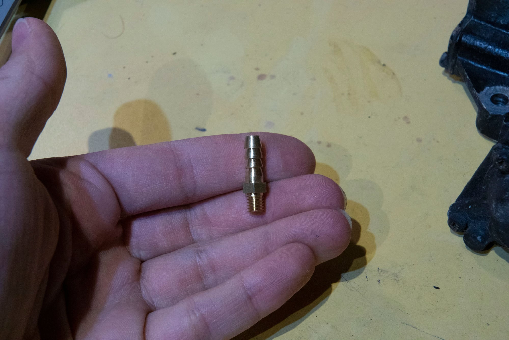
(there's no emoji that properly conveys "terror" so there's my best attempt). Fortunately a more experienced associate was there and immediately jumped in to correct him, but man, if there was no one around and someone tried using garden hose for their fuel system that could have ended in disaster.

So my only option was to buy an absurdly long roll on Amazon that should arrive before the 1st, and that gives me 25' of hose which should last me a long time. I wish I had known this before I disassembled my fuel system, but hey, there are worse things in life than having to wait a couple of days.

Updates to come as soon as I have the parts.

WondrousBread
WondrousBread Reader
7/1/24 8:24 p.m.

The fuel hose was supposed to arrive today, so I started out this morning by mounting the fuel-pressure regulator. Here's the regulator I picked up:


Aeromotive 13109, with vacuum / boost 1:1 reference, port for a pressure sensor, and dual inlets. There are cheaper regulators available but I knew I would want to use the sensor port and dual inlets eventually, so it made sense to just pick up a regulator now that has all the features I would need later.

One thing I noticed is that the threads looked really clean:


That on it's own isn't surprising, but I've seen some knock-off regulators with sketchy threads right out of the box. Yet another reason not to trust your safety to a no-name regulator.

Then I picked up these 3/8" (yes, 3/8", more on that after) barbs and installed them:


And then put this nifty little FPR adapter I found onto the secondary fuel rail:


It was advertised for Subarus, but I've seen similar regulator designs on Hondas as well so I assumed (correctly) that it was a common design for Japanese vehicles.

After that I needed a place to put the regulator. I didn't really want to put it on the firewall because the outlet is at the front of the engine and the hose would have to be very long. I also didn't want it on the exhaust side of the engine for safety reasons. But I found a convenient place where the big air solenoid for the stock ECU used to live, and made a simple little aluminum bracket for it:


Now normally I would connect the outlet from the secondary rail to the inlet of the new regulator, and the outlet of the regulator to the return line. But if you recall earlier I mentioned that I purchased 3/8" barbs. It wasn't just a simple error on my part when purchasing, but an error in measurement.

I noticed my fuel lines fit on the stock barbs at the fuel rails just a little looser than I thought they should. I thought this was because the new fuel lines my dad made when I bought the car (so not "new" but 8 years old) were slightly larger than stock, and the hoses were sized for those lines. I knew the current hose was 5/16" so I wanted to buy the next smaller hose which I determined (incorrectly) to be 3/8". I'm used to the metric system since I live in Canada, but it was still kind of sloppy on my part not to actually do the math and just rely on my faulty assumption.

Turns out it wouldn't have mattered since the stock lines are 8mm anyways, and the closest imperial size is 5/16". So if my lines feel a bit looser than expected it must just be my perception. I was able to reuse my old lines since they were only 2-3 years old and in good shape, plus I used two clamps at each fitting as is my habit. I'm pretty paranoid about fuel.

This does mean I need to wait a couple more days for the fittings to use the Aeromotive regulator, so for now I had to use the stock one. Injector Dynamics makes this handy spreadsheet that calculates the injector characteristics for you:


Stock static pressure without vacuum / boost at the nipple is about 37 psi and this spreadsheet doesn't accept values below 40. So I found the difference in dead time and flow from 43 to 40, and then extrapolated what the values should be for 37 (assuming linearity, which is probably an incorrect assumption). Then I used the voltage and small pulsewidths curves as-is. This is just to get the car driving for a day or two until I can properly plumb the new regulator.

I started it up, played with the Megasquirt's Required Fuel setting (basically a global mixture adjustment) until it looked about right and then went for a drive. First impressions are that it's a little smoother at idle and very light throttle. This is kind of in-line with what I was expecting, although I might see further improvement when I'm running 43.5 psi of pressure and using the correct characteristics from the sheet as intended. That is after all the whole point of this upgrade. I'm not going to do any extensive tuning with the stock regulator anyways since everything will change again once I'm running the correct pressure.

One other thing that I am curious to see is if the increased pressure in the rails helps with idle stability after hot-starts. It isn't like they were terrible before, but it was definitely a bit lumpier if I started it after a few minutes of heat-soak. Mazda had a neat solution to this which was to put a solenoid in the path of the FPRs pressure-reference, and then close this solenoid for 90 seconds on hot-starts. This was to prevent fuel boiling inside the rails (since pressure drops down to < 30 psi when the engine is at idle and the FPR is seeing vacuum). Raising the base pressure to 43.5 psi will also raise the pressure at idle and might improve hot-starts. I would be fine with it if there is no improvement at all, but it should be interesting to see what happens.

Updates as soon as I have the 5/16" barbs I need

WondrousBread
WondrousBread Reader
7/7/24 9:24 p.m.

The new fittings arrived, so I installed those on my FPR and connected up the hoses:


The electrical tape on those two vacuum ports is temporary. The old caps split and the new haven't arrived yet, so this lets me drive the car until then.

Swapped out the original FPR for the adapter piece I showed before:


It works pretty well with two minor caveats:

1. The included o-ring is just slightly undersized. I swapped the o-ring from my original FPR (only a year or two old) and it felt much more secure.

2. The round fitting for the rail and the barb fitting for the hose both require thread sealant. I used Teflon tape to good effect, but there's nothing on it from the factory so it leaked out of both on my first attempt.

I did an impromptu alternator rebuild as well. My alternator was working fine but I heard a squeal on startup the last few days. Seems like the rear bearing was giving up, so I spent about 25 minutes swapping the bearings from a spare 3G alternator I had around:


I noticed the bearings are some brand I've never heard of (WTN, I think) so I'll try and buy some name-brand equivalents so I don't need to worry about this again. My alternator suffered a few more scratches but is now working fine:


The only thing I don't like about my FPR location is that the return hose hits the rear rotor housing:


I've got to do something about that lone wire too. It's just for the coolant temp gauge, but still. All of this wiring will be neatened up when I make a new harness.

With everything hooked up I was able to adjust the regulator to 44psi and update the ECU settings, then I started it up. For some reason I needed about 15% increase in fuel across the entire flow curve to put AFRs back around target (although less would have worked at higher flow rates). I'm not using more fuel with this setup (certainly not 15% more) so I assume this is something to do with my dead-time settings on the stock injectors being an educated guess of 1ms, which kind of skews everything. Now that I have accurate settings with the ID725s the new flow curve should be closer to the actual amount of airflow.

First impressions:

- Idle is definitely smoother. Nothing crazy but a definite improvement
- Transients are smoother.
- Car barely stumbles on hot starts after soaking for 20+ minutes. I think with some tuning of the ASE I can eliminate it completely. Higher pressure might improve this further, but it's good enough now and as discussed a higher rail pressure might make the injectors less linear at idle.
- It's easier to take off from a stop without as much feathering the clutch.

The biggest difference is that the car is happy at much lower throttle amounts and in the 1500-2500 rpm area where I've found the engine to be a bit lumpy in the past. Not that it ran poorly or anything, but it's noticeably smoother when I'm at say 5% throttle cruising along slowly.

I took a long drive and started smoothing out the flow curve even further (15% correction was an estimate, after all) so I might find more improvements are there for the taking. Once the flow curve is smooth I'll revisit all of the compensation tables.

I'm pretty happy with the results so far. There are already noticeable improvements and this prepares me to install an upgraded fuel pump when it comes time to swap the Turbo II engine in.

Until next time :)

fidelity101
fidelity101 UberDork
7/15/24 1:21 p.m.

I don't know how I missed this thread, there is a goldmine of information. I have much more reading to do and I should have chimed in on other parts but it looks like you got those sorted! 

as someone who is in additive manufacturing professionally, its cool to see you use it effectively. 

WondrousBread
WondrousBread Reader
7/21/24 9:01 p.m.

This is less of an update and more of an informational post, and not even about Rx7 parts. But it has some interesting implications for my idea to use an electric air pump + solenoid for the AUX ports so people might enjoy it.

I finally caught COVID last week so I've been stuck at home, and not feeling well enough to do any meaningful work on my car. I did have a part arrive in the mail though. I found that there are plenty of electric air pump options out there and decided on a Toyota Tacoma pump based solely on cost. Full disclosure, this is a new aftermarket part, not OEM. Here's how it came out of the box:


It came with a little plastic dust cover for the inlet (bottom-most tube in this photo) and rubber isolators for the mount. My idea was to build a simple mount, add a tube from the airbox to the inlet, then cap the outlet with a small barb for the AUX ports and use a solenoid to vary the amount of pressure the actuators see. Since it's not linked to crank speed like the belt-driven pump it should avoid the issue I was encountering where pressure was linked to RPM and let me have complete load-based control.

The first thing I noticed was this absurdly large connector with absurdly large terminals inside:


Maybe I should have used a coin for scale. But it's really big. At this point I realized the pump probably draws a significant amount of current, which made we wonder why it only has 14 gauge wire. I know it's only intended to run for 90 seconds at a time, but come on.

The top screw comes out which exposes the filter housing:


The filter isn't necessary for our application since the Rx7 airbox has an outlet on the filtered side for the air pump. You can see the pump impeller peeking out from the bottom of the housing:


The housing comes off with 4 screws and then the impeller is exposed:


Definitely a different design from the Rx7 pump. The Rx7 pump is a rotary vane pump, similar to a power-steering pump if you've ever looked inside one of those. This seems to operate more like a water pump where there is a simple impeller.

The wear on the top of the impeller was there out of the box. There was some molybdenum grease on it, but there were also witness marks on the plastic housing so some wear was definitely occurring:


When the top housing is removed this rubber cap drops off of the motor on the bottom:


When you see the size of this motor you start to really wonder why they thought 14 gauge wire was acceptable. Also, the spade connectors:


I know this isn't OEM, but come on. Aside from being the wrong size terminal, how many amps are we sending through that tiny point of contact?

I can answer that because I tested it. 20 amps continuous, >20 amps startup. Not surprising that you need a lot of power to move significant air but one would expect a little more attention would be paid to the wire sizing. At that point I realized that if I was going to run this pump I would be adding 10 gauge wiring for it, but it became a moot point when I went to test it. This pump moves a good amount of air but it can't build pressure at the outlet the same way the rotary vane pump can. I think this is more to do with the pump design than with the motor sizing. Maybe the impeller type pumps simply aren't good at dealing with pressure on the outlet side. This pump couldn't even budge the AUX actuators.

It's also not surprising that I saw tons of reliability complaints when I searched for electric air pumps. This seems to be true regardless of manufacturer. I think the motor in these pumps has a hard life and gets pretty hot inside that rubber cap with no ventilation. Plus it lives under the hood of a car.

Either way the pump ended up being returned, but most of the other electric air pumps I see on the market are a similar design so I think they're mostly ruled out. It seems like Rx8 pumps might be an option, but at some point the cost of the air pump based solution reaches the cost of the linkage based solution I suggested in the past, so I don't think I'm going to go to the trouble of tracking down an Rx8 pump to see if it works any better. Whether I build out the linkage design or just wire the ports open is still up in the air (although my test shows the fully open ports only become efficient around 6400 rpm so I will be unambiguously down on power almost all the time with open ports, other than when flat-out at high rpm).

Not much of an update, but I learned something from it. Until next time

1 ... 6 7 8 9

You'll need to log in to post.

Our Preferred Partners
FC25Iw1tUbJNKaDFSCyqsyzA2C1KCpvCNVhfBozI2l5zQTIT0LeoIK0wXsUpVMEY