


I am putting a KL series Mazda V6 into one of these:
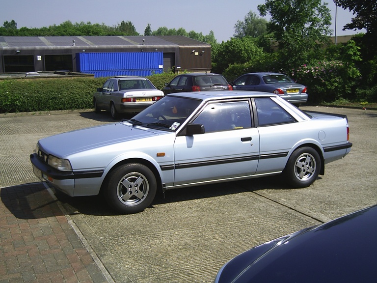
('86 626 Coupe GT)
I'm not worried about the mechanical bits, but because I am a nerd, I desire that the car retain it's goofy 80's digital gauge cluster:

There are aftermarket solutions for tweaking the tach signal, to account for the extra cylinders, so I am not worried about that...
My issue is that although the recipient car and the KL-powered cars share the same transmission innards, the KL cars use a speedometer sensor while the '86 626 uses a speedometer cable. The '86 626 speedometer cable doesn't go into the KL transmission's speedometer sensor hole, either.
Sooo...
Here is a chunk that I liberated from the insides of my digital cluster:

The speedo cable goes into the back and drives a wheel for a hall-effect sensor. You can see the odometer drive on the far side (that's a different issue.) Here's shot of both sides of the board that the hall effect sensor is on. I mirrored the right side so it's easier to see what is going on:

This board sends a signal that gets interpolated into digital numerals, elsewhere in the cluster. If I were to guess, I would think that this board just keeps the voltage pulse that comes from the hall effect sensor inside of a range that can be used by the circuit that decides what digital numerals to display. I see there are a couple resistors and a capacitor there (the bulb portion at the top is obvious and not a concern). But that's about all I know.
With all that said, what I want to do is, create a circuit that takes input from the speedo sensor on the transmission, and outputs an appropriate signal into the board above, or the OUT lead on the board above, making the cluster think that there is still a speedometer cable spinning the hall effect wheel.
I am not asking for a step-by-step on how to do this.
I am just wondering if anyone can point me to some book, forum, website, or other resource which can teach me just enough about the subject at hand to accomplish this.
Is this something that Arduino can do?
Thanks


