I've been scratching my head trying to figure out how to make battery disconnect switch with 2 terminals (cheap) kill the whole car while simultaneously allowing for a charge light but not allowing the alternator output to keep the ignition alive, and I got to wondering why we don't just put the disconnect in the negative cable instead of the positive?
I run the alternator output directly to the battery.
Everything else runs off the switch. When the switch is open, everything else shuts off, but the now inoperable alternator can still "charge" the battery (or, what would have been a voltage spike as the batt is disconnected) as the engine shuts off.

ShawnG
UltimaDork
10/3/21 11:38 p.m.
AngryCorvair (Forum Supporter) said:
I got to wondering why we don't just put the disconnect in the negative cable instead of the positive?
That's where it's always gone in every car I've ever put one in.
Is there a good reason to put it on the positive cable?
Usually it is on the positive so you can run the alternator to the battery side of the switch. That way when the switch is cut off, the alternator can't keep the engine running. Most racing organizations want the battery kill switch to shut off the car, thus the positive side. Personally I think the negative is the better choice.
Our stockcars always had them on the negative side.

Mr_Asa
PowerDork
10/4/21 7:49 a.m.
In reply to AngryCorvair (Forum Supporter) :
Put it on the negative and in the event of a crash the bent metal can pinch through the positive and then you're crashed and on fire.
Freiburger had a great routing system to kill the power, prevent the alternator from charging, and prevent a spike that could damage the alternator. Roadkill Garage episode where they are building his 32 Ford.
The thing about switching positive that's giving me a brain fart is incorporating a charge light, because it has to go between B+ and Alt. Doesn't this create a path through which the alt can keep the ignition alive? I will run without a charge light if I have to, as long as I won't compromise the health of the alternator.
Mr_Asa said:
In reply to AngryCorvair (Forum Supporter) :
Put it on the negative and in the event of a crash the bent metal can pinch through the positive and then you're crashed and on fire.
isn't that risk the same regardless of which side is switched? Crashes bend metal and pinch cables long before safety personnel get there to operate master disconnect.
The charge light runs off the alternator and not the ignition system, right? Wire the alternator to battery, charge light to alternator, and kill switch between b+ and rest of car. Very simple, preserves alternator. Cars where it's new enough to possibly be a problem probably don't have a charge light.
^^^ This.
And your charge light will work fine, and the car won't keep running.
Mr_Asa
PowerDork
10/4/21 9:50 a.m.
AngryCorvair (Forum Supporter) said:
Mr_Asa said:
In reply to AngryCorvair (Forum Supporter) :
Put it on the negative and in the event of a crash the bent metal can pinch through the positive and then you're crashed and on fire.
isn't that risk the same regardless of which side is switched? Crashes bend metal and pinch cables long before safety personnel get there to operate master disconnect.
Fair, but in one case you're going to be able to shut off the power and in the other you wont.

This is an area where I've never found a definitive correct source of information, despite much research . One thing that seems clear is that the switch should go on the B+ side so you can turn off the live current source in the event of a crash.
To pass tech with SCCA, the switch needs to shut off the car when idling at 2,000 RPM. My SM failed tech this spring because the switch interrupted B+ from the battery, but the car was able to run off of alternator current so the switch didn't shut it off. I was in a pinch to get it fixed before race school and I got some help from Panic Motorsports; they pulled wire from the alternator to the switch and disconnected the stock alternator wire. The switch then stopped the car correctly and I passed tech. I've heard (but not experienced) that this method can be hard on alternators and even kill them.
When we built our 24 Hours of Lemons car, we were required to have a 3PST kill switch that simultaneously interrupted B+ from the battery, interrupted the ignition wire in the steering column, and shunted the alternator current through a power resistor to ground. It was a b!tch to wire correctly, but it did its job safely and stopped the car when running. AFAIK this is actually the "correct" way to do it.
Here's a horrible but clear drawing I found online to show how most 2-post kill switches should be wired:
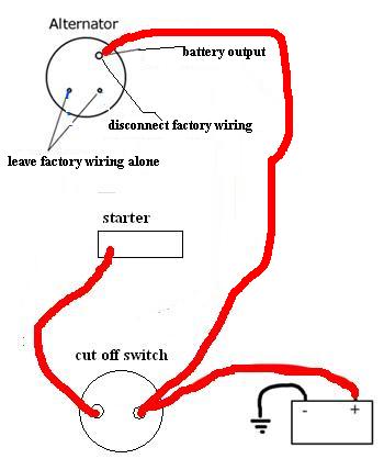
Some people use the kill switch wiring terminal as a junction point for the b+ and alternator lead. I disagree with that, I would wire directly from the battery, through a fuse, to the alternator. Keep the wire run as short as practial and out of the passenger compartment as much as possible. One + wire goes to the kill switch, one + wire goes from the kill switch to your starter and distribution panel. Charge light goes from alternator terminal to dash then on to ground, no need for it to interact with the ignition system at all.
Starter, alt and battery all on one side of the switch. Everything else on the other side. Done.
I appreciate all the input. Thanks!
charge light complicates it in my mind because it is illuminated by a voltage difference between loaded battery (typically at the B+ input to ignition switch) and field current terminal of alternator. I don't know enough about alternator construction to know if there's a backfeed path from alternator output to the field current terminal. If there is, then that path could keep the ignition alive (because ignition switch is in Run) after the master is disconnected.
i'm thinking that an appropriately-spec'd diode in the wire between charge light and ignition would eliminate the backfeed concern. off to search mouser.com


