I think he needs to go to a crank trigger wheel somehow, but then we're starting to defeat the purpose of the DIYPNP aspect.
Beyond that, i'm kinda Megasquirt stupid and once we start talking about EDIS, my eyes start glazing over. ![]()
I think he needs to go to a crank trigger wheel somehow, but then we're starting to defeat the purpose of the DIYPNP aspect.
Beyond that, i'm kinda Megasquirt stupid and once we start talking about EDIS, my eyes start glazing over. ![]()
RossD wrote: What about ditching one of the sensors? Ford's EDIS only uses one...
That was exactly where I was going with this.
Another dumb question but have you looked at fuel pressure? Are you sure it is lose of spark / sync?
Diodes will not provide the filtering you are looking for. If you've got current going in the "wrong" direction, there's another issue.
http://img236.imageshack.us/img236/8944/dist14dl.jpg Here's a link to a Dizzy Diagram for the F2T. The Ying Yang looking part is the Crank Sensor (#1 & #4 Cylinder Position Sensor) and the 24 Tooth wheel under it is the 24 Tooth Ne (Next Event) Sensor. Where can I host a Logs at online top post?
In reply to dansxr2:
So, if I have this right the Ne produces 24 pulses per crank rotation. Since it is on the distributor and that appears to be operating at cam rotation speed (half the crank) I am guessing the wheel is actually a 48 tooth wheel and it has no missing tooth or other bit on it to identify TDC...that is done by G1 (which also detects the beginning of the engine cycle - Cylinder 1 at TDC after compression).
Since G1 and the psuedo crank sensor (the Ne wheel) are on the same shaft I would bet they 1) do not have any movement relative to each other and 2) are not on some sort of mechanical distributor advance plate.
If the 48 tooth wheel doesnt have a missing tooth, you cannot drop the G1 (or G2) input to the MS and just drop back to a wasted spark/semi sequential injection mode. The Ne does not have any provision to detect TDC.
So, since you cant change the physical relationship between G1 and Ne to resolve the timing issue with the MS, and you cannot skip the G1 input, perhaps the TS suggestions are your only recourse...altering the timing relationship of the signals from each. One of the TS suggestions was to switch the trigger edge from the Ne wheel that being used by MS for timing to initiate spark and injection. While the Ne wheel design probably produced leading and trailing edge signals that are close together because the wheel has teeth more like triangles than squares it is the better of the 2 options to try because the G rotor appears to have no defined "edge" on one side of the trigger wheel.
You will need to calculate how many degrees from TDC the "other" edge of the 48 tooth trigger wheel is and input hat into the MS or it will be injecting and sparking in error by that number of degrees...At least that is how the regular MS3 would do it. These MSPnP things may be set up differently by default (assuming PnP really means just that). The folks at DIYAutoTune might be able to clarify this for you.
You need to modify your distributor, it will make your life easier heres a link
not mine i copied it
http://www.performanceprobe.com/forum/showthread.php?t=30888
modifying the turbo distributor.
NOTE: This is currently for the 88-89 ONLY!! 90-92 WILL be posted soon!!!!
For Megasquirt, we need a RPM input. The simplest way to achieve this input on the turbo engine, is using the factory VR sensor and trigger wheel. BUT, in order to do this, we must modify the factory 24-tooth wheel so the VR sensor can provide the signal in terms that Megasquirt can recognize. Since RPM is based on the rotations of the crankshaft, and the pick-up wheel is located in the distributor where the camshaft turns at half the speed of the crank, we must set up the distributor in a way to "trick" the MS in to thinking we are triggering off the crank. We can achieve this by removing two teeth from the factory pick-up wheel in the distributor. This spits the wheel in half, giving us a 12-1 wheel (11 teeth, one missing). This allows us to split the cam cycle into two separate cycles to match the crankshaft. The first tooth starts the ignition pick-up cycle, and the missing tooth signals for the megasquirt to "start over" the ignition event.
To start the modifications, remove the cap, rotor, and protective cap.
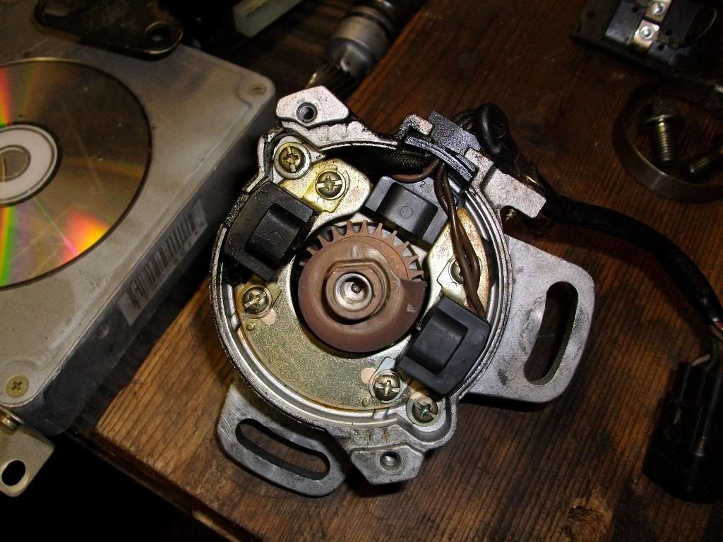
Remove the two sensors on top by first removing the 4 Phillips screws (2 per sensor). Then cut the wires attached to the sensor and discard them.
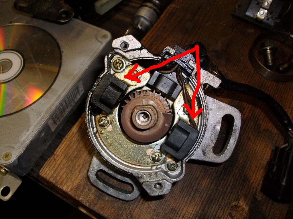
You should now have this:
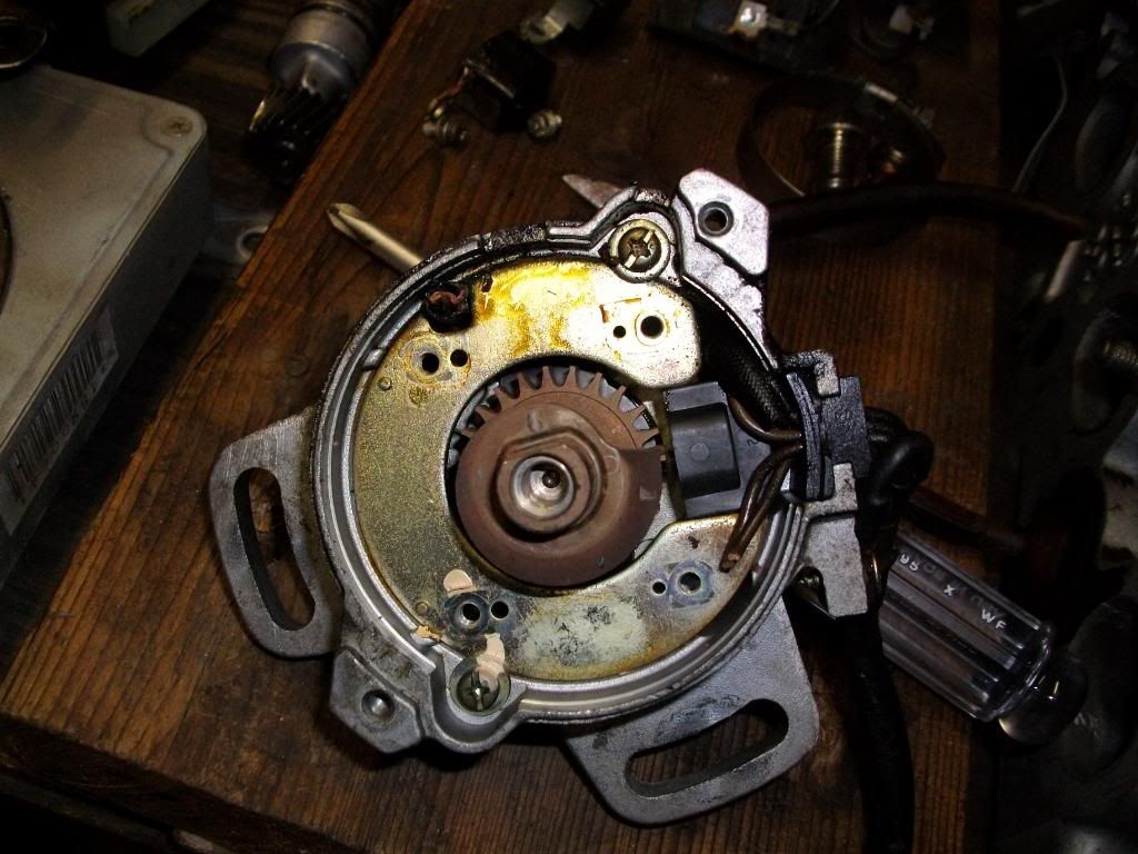
Next, remove the “spacer plate” retaining screws. Lift out the plate and discard.
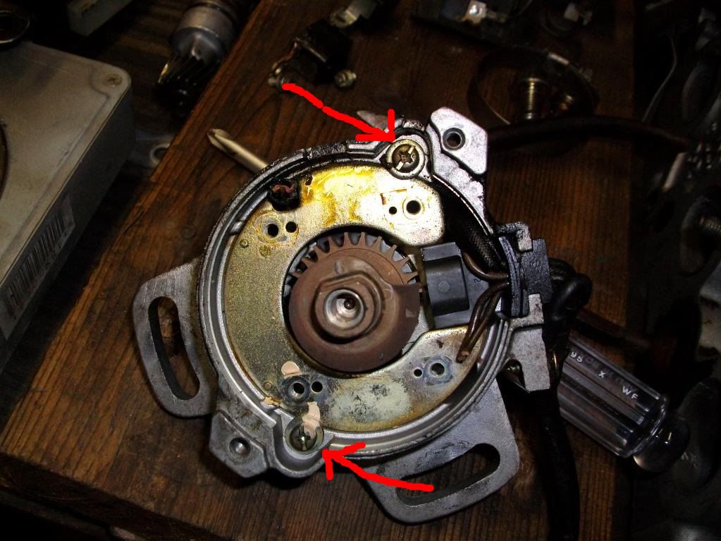
Next, remove pin from drive “gear” on the cam side of the distributor. You can use a hammer and punch. Using a sharpie or equivalent, make a spot on the “gear” and the shaft, this way you can re0assemble them back together correctly.
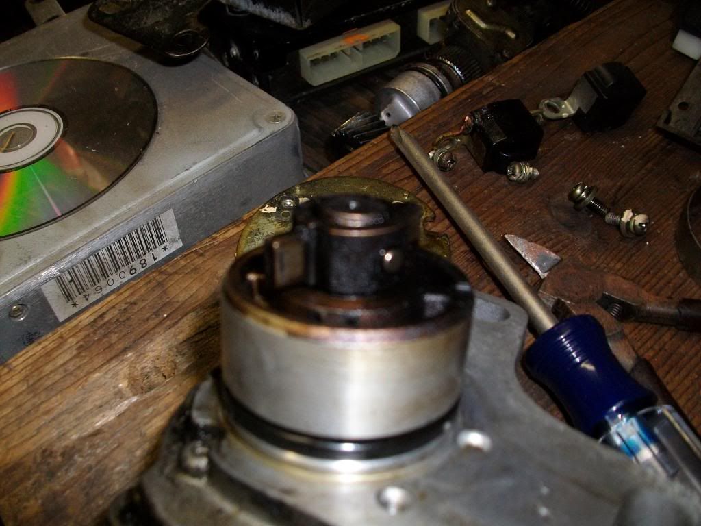
Inside the distributor, remove the two phillips screws at the bottom. This holds in the center shaft. Once removed, you should be able to easily remove the distributor shaft.
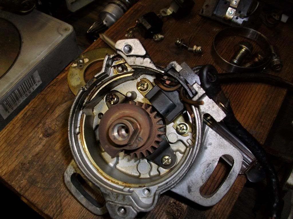
We can now modify the distributor to work with megasquirt. We want to modify the bottom wheel, not the top. You want to grind down two of the “teeth”. Looking at the top wheel, at the point, count back four teeth. We want to remove the forth tooth. Mark this tooth.
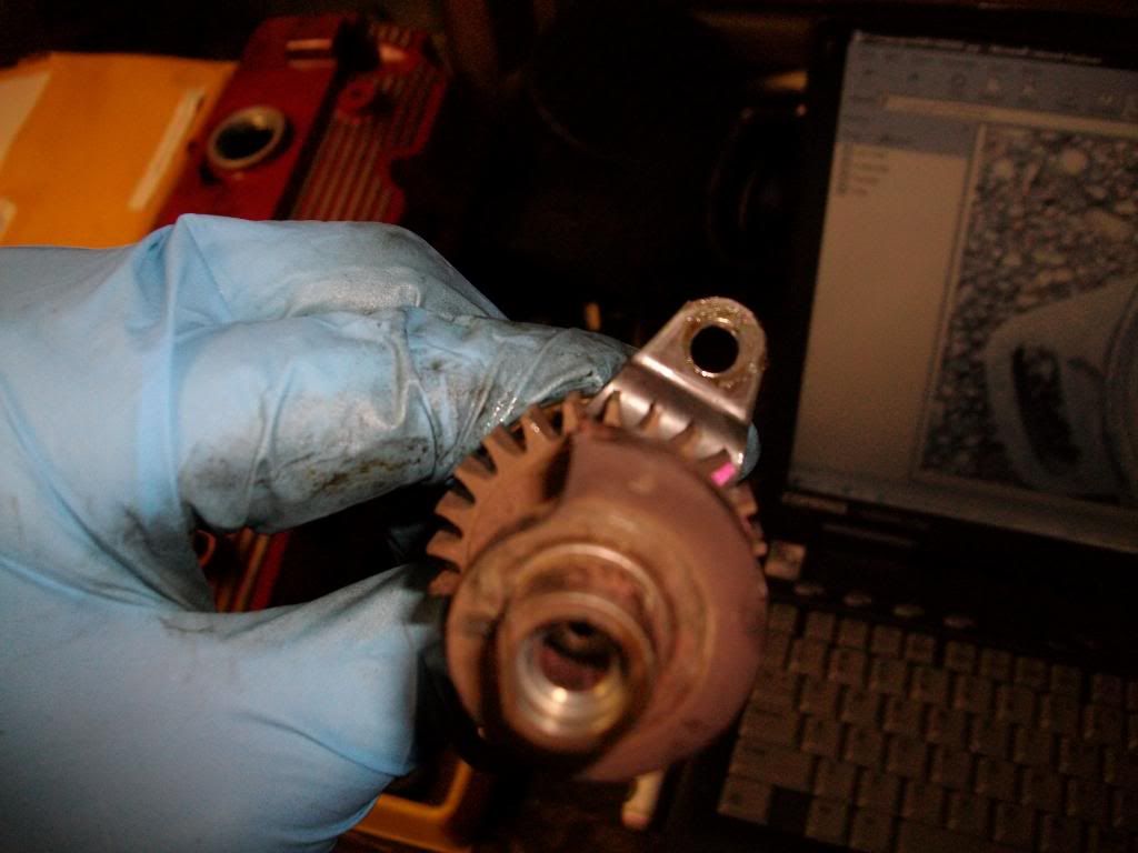
We also want to remove the tooth directly opposite of this one. Count 12 teeth (in either direction). Make the 12th tooth. Make this tooth, as we want to remove this one as well. You should have 11 teeth between the two marked teeth on both directions.
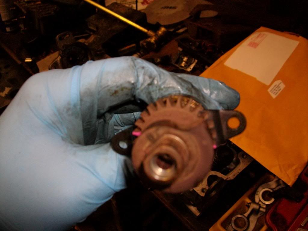
Now, grind down the two teeth. You can use a Dremal tool, a drill with a grinding/cutting bit, air tool, etc. TAKE YOUR TIME! Go slow and take off a little at a time. We are working in a small space with very little material, and you DO NOT want to damage the surrounding teeth. If you happen to “nudge” one, its no big deal, just try to avoid them as much as possible.
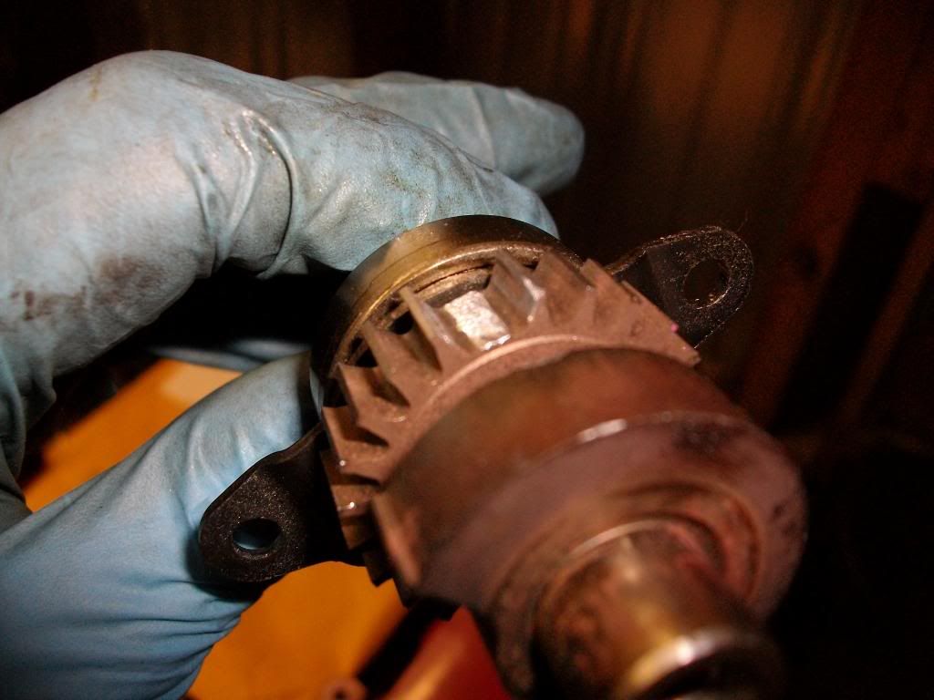
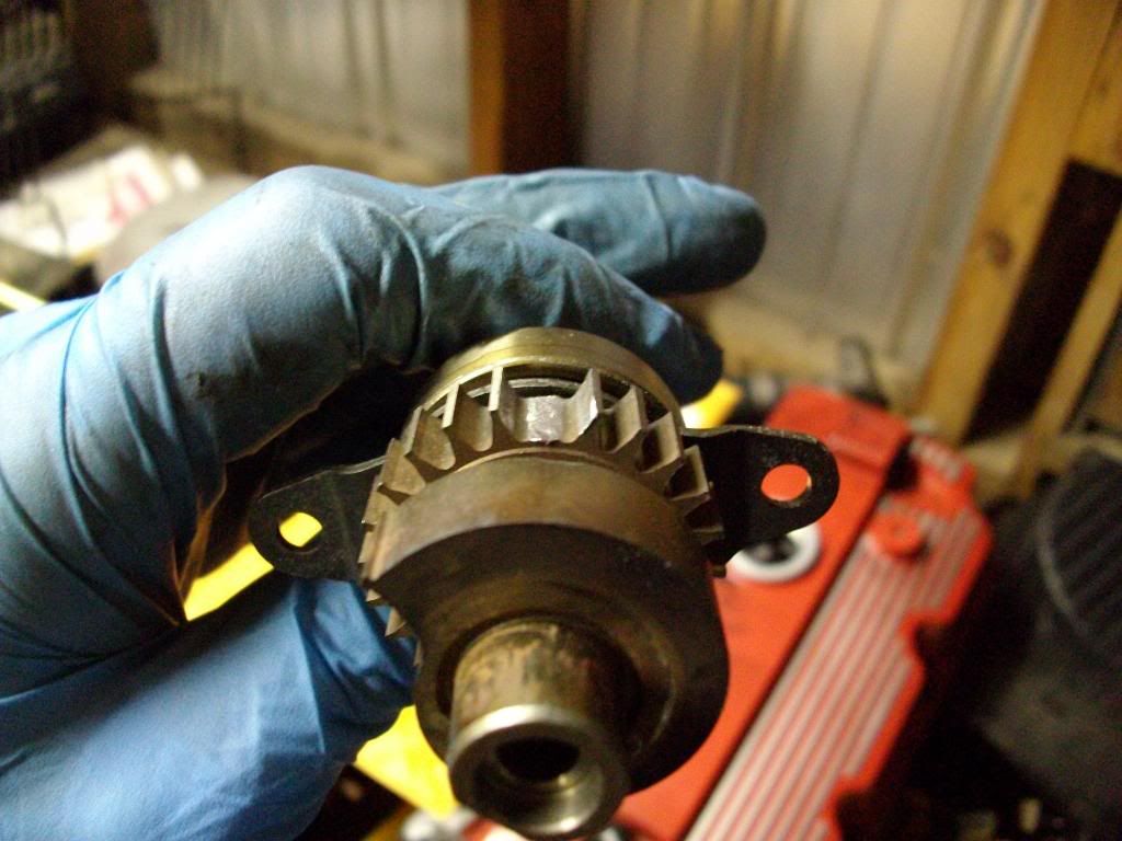
Once this is complete, clean the distributor shaft of ALL metal shavings. Re-assemble the distributor shaft into the distributor housing. Install mounting screws. Reinstall the distributor drive gear and retaining pin. Be sure to line up the marks you made earlier.
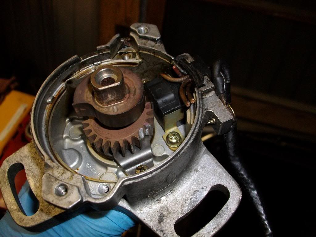
In reply to Caleb:
Yup, that should work. I see you are setting the missing tooth (teeth) about 60 degrees BTDC.
So, it Is a 24 tooth trigger e.g. 12 per crank rotation and not 24 per rotation as I thought I read. That is about 1/3 of what MS recommends. Any issues with injection or ignition timing ?
I would put a 72 tooth spur gear on top of that and then remove 2 teeth 90 deg from each other. With this you can go EDIS. If This is what I did on my 924s and it works brilliantly. You will have to add a sensor as well but that is simple. Use one from a RX7. Dan I probably have all of this sitting on the shelf if you need it.
If you can get away with only 48 teeth McMaster car sells this spur gear that would work. Part # 6867K24
web page is here >>>http://www.mcmaster.com/#spur-gears/=kkty09 bolt on to the distributor mount a sensor remove a tooth and off you go.
This is just the sorta thing I was hoping to avoid by purchasing the DIYPnP... :-/ theres no correct way the car will run right without modifying the distributor? Is this whats makin my car run like E36 M3?
This is one of those things that SHOULD work with the MS as is, but it appears to be having issues with noise. Do you have a fresh composite log of where you're at now with crank and cam signals?
Have you checked your grounds and ensured the wires for the pickups are properly shielded with the shields grounded on one end only?
You could perhaps try disconnecting the alternator, start it up and see if the noise problem goes away. Sometimes an alternator can cause a bunch of noise.
I'm with Matt, on your install it seems something is just not working right. Troubleshoot it, don't reinvent the wheel.
The purpose of the diodes is to 'catch' the reverse EMF spike generated when the injector pintle slams home.
Injectors are essentially solenoids. When the injector pulse current flows through the coil, it generates a magnetic field that pulls the injector pintle open and allows fuel to pass. When the pulse ends, there is still a magnetic field that must collapse. When the pintle slams home, any residual magnetic field collapses suddenly, creating a large short voltage spike (often hundreds of volts!).
These spikes can cause noise that will 'false trigger' logic and sensor circuits.
This fix only works with DC circuits, and you must install the diode accross the coil terminals in the correct direction, otherwise it just shorts out the injector pulse.
BTW, this is all 'old guy' stuff, we've been using catch diodes on relay coils and other electromechanical devices for more than 50 years now. ;)
Carter
Do you have any AFR readings? Is it that the car just runs like crap because it does not have a tune?
Even the PNP systems need to be tuned.
If the car starts and runs, but does not rev high you are getting a tach signal. Does the tach signal (rpm reading) on the laptop match that on the dash?
RossD wrote: What about ditching one of the sensors? Ford's EDIS only uses one...
EDIS doesn't need to know, but the ECU on sequential (SEFI) setups needs to know whether or not to squirt, and uses a cam position sensor.
On batch injection setups, no cam sensor is needed.
Carter
Yes the tach reading works, and I have a basemap loaded. The RPM signal goes haywire from ~2000-0 and everywhere in between. My laptop is giving me some issues and I'm goin to take it to be looked at right now. I have an AEM UEGO thats not hooked up into the ECU as an input, because the factory ecu uses a 0-1v range opposed to the AEM's 0-5v.
Yes, a composite log is what I had in mind. We've had this running fine on a later F2T, but different distributors and wiring may be a little different...
Erohslc: there is a dedicated flyback circuit in the ms injector driver to deal with the back emf from the injectors, and its a bit fancier then some random diodes!
Does the rpm jump if you crank with the coil and/or injectors unplugged?
I'd call up DIYAT before grinding anything, they've always been helpful. I'd also check the MS specific forums for any info or even post there, very smart and helpful people.
Aside from that, I'd make sure that your indicated timing matches your commanded timing and all the other standard stuff.
What is the infatuation with EDIS? I see it on other boards too. MS2 can control wasted spark(up to 12 cyl I think?) and sequential up to 6cyl WITHOUT any EDIS parts, in fact I'd argue that it's easier to do without EDIS because you can go with something other than 36-1 for the trigger wheel.
On the diodes again, they work great for motors and such things that don't have specific timing requirements, but on an injector, they will allow the current to circulate through the coil and the diode, holding the pintle open for longer than desired. Long opening/closing times are BAD.
EDIS works great for cars with very old ignition systems and it is easier to setup and tune from scratch as the EDIS controller can provide a stable 10degrees of timing to allow you to get the fuel dialed in. Most of the EDIS infatuation comes from working with MS1 or MSnS and for many of the folks rolling their own MS install, it is sometimes a daunting task trying to mate MS to the stock ignition system, so an EDIS system is relatively easy to install.
EDIS also seems to mean "wasted spark" in a generic term as in the recomendation isn't to use the EDIS parts directly, but to configure the system to work similarly to EDIS (36-1, sensor, coilpack) as it is a known quantity to work with.
Ultimately, you do want to move to controlling the coil directly from the MS board and MS1 can do it with the proper mods and code. MS2+ obviously can as well.
I know on my 924, the EDIS module is still in place because it drives the stock tach quite well. If I remove it, I'd have to build a circuit to drive the tach, which I've not seen a ready made circuit that works yet and the car isn't anywhere near tuned well enough to notice the gain in moving to direct control of the coil by MegaSquirt.
You'll need to log in to post.