
It seems that most FWD cars use 4 engine mounts: Two on the ends of the drivetrain that support the weight of the engine and transmission, and one each on the front and back to resist the torque created when accelerating or engine braking.
The Dodge Neon engine I am using for my project was slightly different. It had a similar setup for the left and right mounts to support the weight of the drivetrain, but then had a top and bottom torque link attached between the "front" of the engine (crank pulley side) and the chassis. Because I don't want to transmit all of these torque forces to one side of my car's tube chassis (and thus have to make one side way beefier than the other) I am converting it to the more conventional layout.
My question is: what does the rear torque mount do? It is right next to the axle, so it seems like it would provide very little torque resistance since it has a very short lever arm to act with. The front arm seems like it would do the bulk of the work, being much farther from the axle. I am trying to decide if I need to design a rear mount into my car, or if the front one will be sufficient.
Here is my proposed front torque link design. I still need to add some tubes to reinforce the chassis in the vertical direction.

TL:DR: What is the point of the rear engine mount on a FWD engine.

Actually, it does a lot. If you think about what happens under acceleration, the axles will try to twist the drivetrain backwards with the differential trying to crawl up the back of the transaxle. The only things keeping the twisting load at bay will be the front mount and that rear mount. The Neon mounts are notoriously soft at normal power levels (trying desperately to reduce the NVH of the 4-cylinders), the SRT-4's were even worse due to the large amount of power available.
Many of the FWD Turbo-Dodge racers with dual purpose cars have found that making the front mount a little stiffer is okay and doesn't impact daily driving too much as long as the rear mount is much more solid and adjustable allowing them to lengthen and stiffen the rear mount for track/drag racing to reduce the stress on the inner CV joints by keeping the axles and CV joints more straight. Some even preload the solution to set the axle height to match the suspension height at launch.
FWD turbo-dodges with automatics typically eliminated that rear mount since the peak torque loads from zero are quite a bit lower (unless you're brake standing or neutral dropping the mofo, heh). So while you might get away without that rear mount in your use with the lighter weight of the car and leveraging stiffer mounts, I'd wait to try it with and without before writing it off completely.
I'd be very wary of making any FWD engine mounting solution less beefy...they tend to be either barely adequate or woefully inadequate. My Corolla has 5 mounts (usual 4 + center, connecting the bellhousing to the crossmember) and it's much closer to the latter.
This car won't break traction as easily as what that powertrain came out of so you'll need an even stronger engine mount solution. I'd recommend adding an engine damper somewhere...some companies make universal engine dampers, or if that's not an option an MTB shock will do.
BTW, I should note that even the Fiat 128/X-1/9 used a torque arm attached from the the top of the transaxle to the chassis rail and they aren't known to be overly powerful or heavy vehicles.

wae
Reader
2/18/14 12:31 p.m.
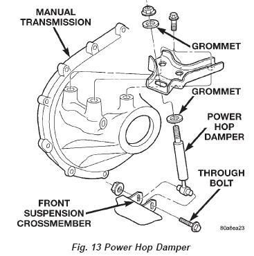
Yeah, if when you're talking front/rear/left/right you're referring to how the motor was originally installed in a Neon relative to the car itself, the "rear" would be the exhaust manifold side of the engine. On A/T cars, there was no mount there -- it was the transmission mount, the front mount, plus the passenger-side mount that did all the work. For an M/T car you'd get more rotation of the engine around its axis, so they added what they called the "bobble strut" that went from a bracket that attaches to the top of the transmission to a holder that was part of the K-member. It was a little piston assembly, similar to a strut that you might use to hold up a hatch. There are some solid bobble kits out there, bobble relocation kits, and some homebrew things to add some stiffness. I can tell you that by spending under ten bucks, I built a solid bobble mount out of a large eye-bolt, a rubber stopper, and some misc. nuts and bolts. The threaded end of the eye bolt goes through the bobble bracket on the transmission, and I stuffed a rubber stopper through the eye and then ran a bolt through that to attach it to the bracket on the K-member. I've got the thing preloaded about as far forward as it will go, and it has reduced the wheel-hop of the car noticeably. I've also filled the rest of the mounts with urethane, so that helps a lot too.
To more directly answer your question, though, the three "mounts" support the engine and handle most of the stress. The bobble strut just gives a little extra cushion as the engine rotates, but can be made to nearly eliminate that rotation.
In reply to turboswede:
Thanks, good info. I guess that makes sense. In a hard launch the front mount is pulling the front of the engine down, but with no rear mount the rear of the engine will start to drop.
I am planning to use the stock mounts, but with urethane filling the air gaps or possibly even removing the rubber and replacing it with urethane.
Good move to fill with urethane but I'd still recommend a damper. It'll kill a lot of the vibration the filled mounts would introduce, and extend the life of the mounts further.
The Toyota RunX/Allex (JDM 2ZZ-powered hatch/wagon thing) comes from the factory with a damper.
In reply to wae:
Thanks for the bobble strut lead. That looks like it would be a lot easier to integrate than a large, rubber mount.
Does anybody see an issue with the toque mount I have pictured in my first post? I have had some concerns expressed that the mount may try to twist left/right, or fore/aft under load, but I am not seeing it myself.
The mount relies on the side mounts to locate the drivetrain side to side. The CV joints will accommodate some movement, so its not a huge issue, IMO.
For example, look at what RWD drivetrains go through under heavy load. Its the nature of the beast and unless you integrate the drive train into the chassis either as a stressed member or just using solid mounts, you'll always get movement under load.
One of your concerns is all the torque going to one side of the frame. Now you are transmitting all that torque to the middle of an unsupported tube. On the factory setup, the top mount goes to the strut tower, the other mounts near the lower control arm mounting bolt. I think that is going to be sturdier than moving it to the middle, with no need for reinforcement. You might have to fab up a spot for the upper mount, but the lower should have something sturdy nearby.
Supports for that tube are in the works. Support tubes will run from each side of the triangular mount bracket to the tops of the diagonals above the mount. I just want to make sure there is not a fatal flaw to my mounts before I weld everything in.

Hal
SuperDork
2/19/14 6:07 p.m.
The Ford Focus uses 3 mounts. Left and right motor mounts and a rear mount. The rear mount (called a dogbone) looks like the mount in your picture. That rear mount goes from the diff to the subframe. So I think your idea would work but you would need to reposition it so that it is parallel to the ground( both ends in the same horizontal plane).
All I know is that when I converted my MKII GTI to a poly filled front mount I didn't notice a big vibration difference. When I did the same modification to the rear mount it rattled all my filings out. The GTech (remember those things?) would not work because the dash it was mounted to vibrated so badly. I could barely read the speedometer and radio display because of the blur.
I went back to the factory Heavy Duty rear mount after that.
That Focus mount looks like it is designed to resist a bending force at the rear cross member, where as my dogbone is only designed for axial forces.
My googlefu is failing trying to figure out how the MKII mounts work.
Here is the final version of my proposed front torque mount. Nothing is welded yet incase there is a fatal flaw I am not seeing. I have added vertical support tubes to strengthen the mount.

Here is a view from the side.

As you can see the mount is perpendicular (or normal for us enginerds) to the axle. Since the mount can pivot on both ends it can only impart force along its axis. If it was not perpendicular to the point of rotation it would want to shove the engine forward or backwards in addition to resisting the torque forces of the engine.
Since it has been controversial I will hold off on welding it in for a few days so I can mull it over a bit more.
Looks good to me. In fact this is probably the most thought I've seen put into a custom engine mount.
Hal
SuperDork
2/20/14 1:45 p.m.
bgkast wrote:
That Focus mount looks like it is designed to resist a bending force at the rear cross member, where as my dogbone is only designed for axial forces.
No bending forces in the Focus mount. It is mounted low on the diff and the only forces are a "stretching force" when the engine tries to rotate around on the left and right motor mounts. I think that your mount will work if it is set up that way.
Just keep in mind that the axis of rotation of the whole motor/trans package is a line between the left and right motor mounts not around the axle.


