


Trying to find schematics/diagram for the CPS on this motor.
Found this.

Is CKPRTN the signal, and CKP2 12V+?

Trying to find schematics/diagram for the CPS on this motor.
Found this.
Is CKPRTN the signal, and CKP2 12V+?
Looks like CKP2 is the signal and CKPRTN is referance voltage..
Thanks! How sure are we and what's your source? ![]()
I was partially wrong now that I double checked which sensor you are talking about.. That diagram is miss leading...
The crank sensor on the 2.5's down at the crank shaft is a VR sensor, not a Hall effect sensor... It has no reference voltage... CKP2 is the (+) side of the signal, CKPRTN is the (-) side of the signal... both feed back to the computer... Ground is the shielding wire that wraps around both wires and gets grounded to either the block or chassis.. they do this to reduce the noise i the circuit..
The green trace is what the signal looks like when using the older DE 6 point crank balancer...
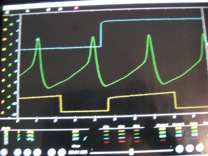
For a fun challenge... The complete capture is 10ms long... On the green trace there are 6 spikes per 1 revolution of the engine.. The spikes are all evenly spaced.. Approximately what rpm was the motor spinning when I took that capture.. :)
4000rpms. ![]()
10ms = 4 spikes
60000ms = 24000
24000 / 6 = 4000
Thanks for the help!!!!
You'll need to log in to post.


