oldeskewltoy said:Fun to follow.......
The new lines came out rather nice......... (2 panel to better see shape...)

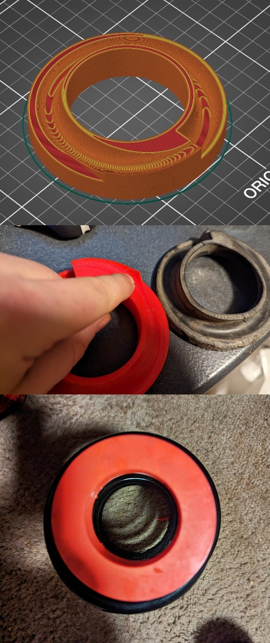
waiting on the 3D printed urethane spring seats - test piece looks good, I've asked that they be printed in black.
oldeskewltoy said:Fun to follow.......
The new lines came out rather nice......... (2 panel to better see shape...)

waiting on the 3D printed urethane spring seats - test piece looks good, I've asked that they be printed in black.

oldeskewltoy said:waiting on the 3D printed urethane spring seats - test piece looks good, I've asked that they be printed in black.
One small issue.... If you look at the bottom image, the inner hole that fits on the post, has a sharp edge..... While the base of the post is radiused.... and has a slight slope (right side of post) as it bends to follow the frame rail.

So I added an inner radius, and I added a slope...

This is how it fits - with no weight on it, once the cars weight is on it - it should all be tight. For the photo I'm holding it in place with my knee....

Last.... I showed the 3 panel to the MX Corona Fb group from Australia... I have about 10-12 interested parties........
more to come.......
It's been over 3 years for this...... it's first fitment.

Fitment will require some Car Craft (the folks who built the BOSS 429 Mustangs) type chassis modifications....
right (passenger) side...
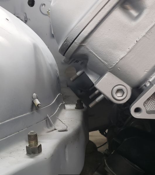
Left (driver) side...
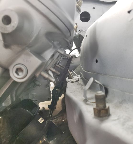
And engine bay view - dotted lines on frame rails are the approximate location of the mods required...

Now... some discussion on adding clearance. There is some room to lift the engine a bit higher - right now there is 4"-4 1/2" of clearance between the top of the throttle body and the hood, but I don't want to raise it too much - I'm afraid to harm the handling balance by having a CG too high. I estimated we have 3/4" of an inch, to 1 " of room before the engine is too high......
wow that is close!!
Hood clearance is one thing, how much trans tunnel room do you have?
One of the mistakes I made with "Colin" was making the trans tunnel TOO high... fitting the HVAC is impossible now. I wanted to make it so the engine and trans could be pulled as an assembly, might have gone overboard.
What is behind the inner fender there?
oldeskewltoy said:
Fitment will require some Car Craft (the folks who built the BOSS 429 Mustangs) type chassis modifications....
Stepping back to page 3 of this thread:
oldeskewltoy said:so...the entire front suspension, and engine mounts are part of the front cradle/cross member assembly... drop the pitman arm, idler arm, brake lines and 4 bolts... and the entire front cradle/cross member comes out as a unit!
The entirety of the front suspension mounts on that crossmember, which then attaches to the body (frame rails) via big rubber bushings and those four big bolts at your 21-3/4" and 25" indicators. Preserving strength in that area is important. That said, I would have no problem cutting back the top and inside wall of those rails an inch or inch and a half and then closing off the resulting holes with sheet metal, creating a 45° bevel, to buy a little room for headers. You could do the same thing aft of the rearmost crossmember for the last primary tube on each head. You may end up wanting to raise the engine mounts a little but I doubt you would need to.
No matter what you do to the body/chassis, headers are probably going to be tough to fit with the engine in place, especially with those extra long studs sticking out of the engine.
Did you ever find a place to cut the header flanges?
In reply to oldeskewltoy :
I'd put a tube reinforcement from the firewall on each side up high forward, then curve down to the "frame rail" just in front of those dotted lines and the bolt through location for the cradle. Maybe another tube from that down to the rail just in back of the back bolt for the cradle. Then you can slice and dice as needed..
Kendall - I'm hoping to accomplish the mods without adding obvious reinforcement...... (edit) would have helped if I read it through... yes it makes a LOT of sense to mount supports to keep the cut part stabile during surgery.........
Pete - the tunnel has already been cut, and while there has not yet been permanent movement of the tunnel, if it needs to move so be it. If you remember the crazy heater that came with the car.... and the purchase of the correct, yet damaged heater box... and I have another with the parts car....
If need be there are aftermarket options.... https://www.google.com/search?q=aftermarket+automotive+heater&tbm=shop&sa=X&ved
DarkMonohue - for chassis rail modification ideas so far we have 2 that should retain most/much of the chassis strength.
1) between the dotted lines from dimension photo above - the spot welds are drilled on the vertical surface, and the frame rail is split (see new photo) lengthwise. The now cut upper part of the frame rail is tucked inside the lower section lowering the upper horizontal surface to gain room. Once the upper part is lowered (nestled) into the lower section and welded (making inner section of lowered frame double thick) the vertical surface then get re-welded. This method requires just some cuts, and drilled spot welds - it also retains (length wise) its original shape so it should fit the odd shape (bends) of the inner fender. The rear bolt inner support would also need to be shortened appropriately. Last would be how to tie in the open ends.... although small plates could be cut and welded in

2) to make the entire run a right triangle - shorten the rear bolt inner support and build a tie-in to the triangle - possibly burying the bolt below the hypotenuse angle
I have not yet had the header flanges made... 1 step at a time. As far as the exhaust studs - they can go, and replaced with either smaller studs, or bolts (wire tied)
In reply to oldeskewltoy :
FWIW, if you have to cut / reposition see if you can make it stronger since you are adding considerably more power.
In reply to L5wolvesf :
that is the intention.... although the engine sits on the cradle, and the cradle carries full front suspension, brakes, and steering rack, as well as the engine. The body rides above the cradle... but still it needs to be at least as rigid as it currently is to hold up to the turning, and braking stress put on the 4 bolt mounts.
got the first estimate today... 35 hours. The current rail is 3 1/4" tall, plan is to halve the height. I've got 7 weeks to get the rear suspension in, engine out, front suspension refreshed so that he can pick it up with his flat bed.
Some fresh photos....

disregard the brush... it is being used to prop up the booster/master cylinder assembly


more to come..... ![]()
In reply to Pete. (l33t FS) :
Agreed. And for every worrywart wringing their hands in despair about chassis strength, there are probably a hundred Swiss-cheesed, acid-dipped, trans braked, big-block American compacts pounding around not giving a damn.
Whatever you do will be strong enough.
Well... at the other end...... once on her wheels, I'll torque the mounting bolts

more to come...... ![]()
oldeskewltoy said:Finally......... These guys are doing the axle swap, and are also likely going to be doing the body. They are Facebook heavy, so if you want to see their work in progress you can follow them here - https://www.facebook.com/brosseauscoachworks
hopefully.... more to come......
So Kent finally managed to find some time to come out and look at the header/inner fender/frame rail issue. As he can do both frame/metal work, and header construction. This was his proposal... "L" brace the frame rail, and flatten the inner fender (cut, and replace)


waiting to hear back on the costs.......
more to come...... ![]()
So a few weeks back when I first dropped the engine in it was determined that there was about 4"(+ or -) from the throttle body top to the hood. What had not yet been determined is distributor to hood clearance as this funky distributor is quite tall.......

....and it is further forward where the hood is sloping down.
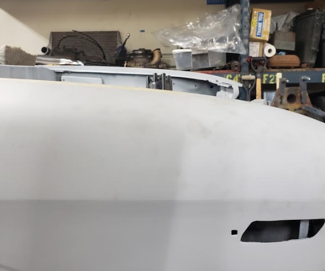
And it does get close....

...roughly 1/4" from cross section of the inner reinforcement....

So the short answer - the hood will not need a bulge, or significant modification, AND I can keep the distributor. No need to run the broken distributor as the cam sensor - and then run either COPS, or short wired coils (ala LS type)
The inner support of the hood will possibly need one of two possible changes.
Change 1 would be the simplest, just the rolled section would be removed - this should gain about 1/2"-5/8"

The 2nd choice would be more drastic... removing nearly the whole center section and then running a new curved piece in its place.

more to come...... ![]()
So with the hood fitting and a plan for the front engine bay, and headers, I'm feeling better about progress, so I dig into the front suspension, and brakes....
Before I go on... I must keep thanking the storage in Cally gods who watched over this car... every nut and bolt came free, there was no hard banging, or cursing, or blood!


As you can see... front suspension mounts to that big front end cradle/subframe, you can also see where the original idler arm mounted.
I'll get to the driverside this weekend...
More to come.... ![]()
oldeskewltoy said:
I'll get to the driverside this weekend...
More to come....
A bit longer... but driverside is now dismantled....

next step... get it blasted... and then decide on powder coating, or 2 stage paint....
more to come........ ![]()
So besides dismantling the front end, I also managed to 1) find a master cylinder rebuild kit, and, 2) found a shop (Karps Power Brake) who can rebuild both the master, and the booster.
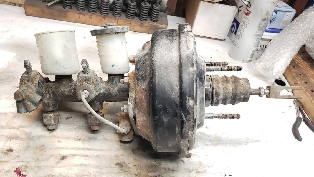
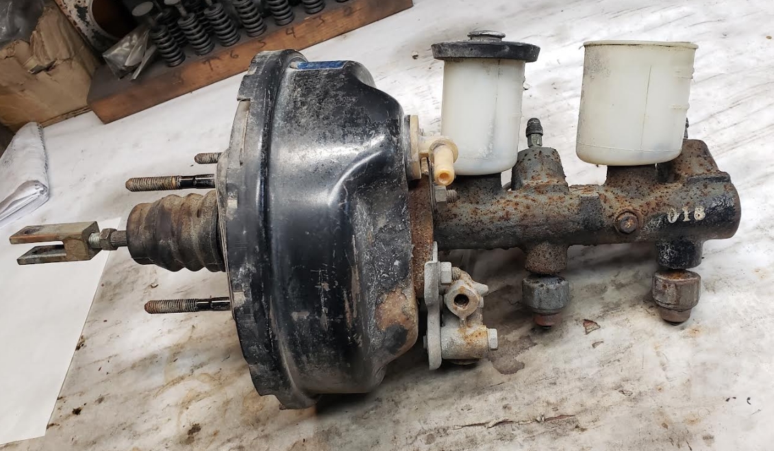

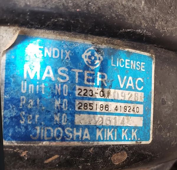
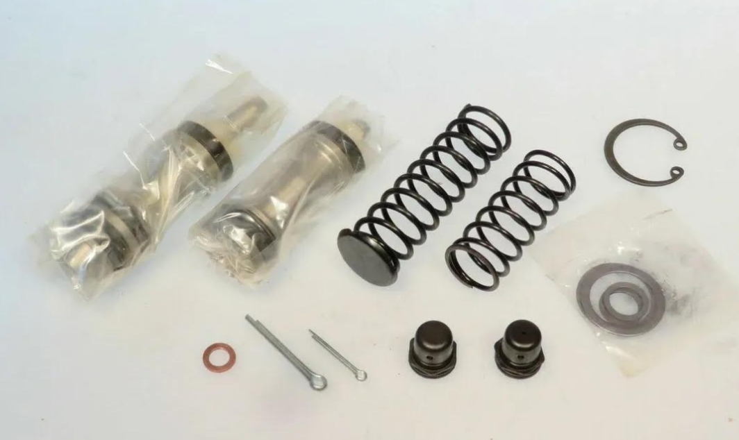
more to come.....![]()
So managed to get the front suspension further broken down..... (all the ball joints are now gone - trashed - the bump stops have been saved - single nut)
I've decided to have these pieces powder coated - it should hold up better then paint.

Track rod - this should provide me a starting point for re-install
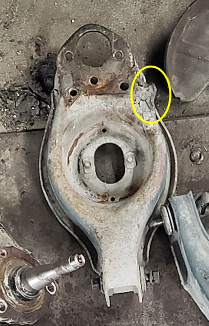
Also noting that the LCAs are almost symmetrical - the tang for the steering stop is the non symmetrical part. This one is lower passenger side
the spindle and steering/tie rod mount with steering stop noted

more to come...... ![]()
The ball joint mounting holes are not symmetrical on that arm. Maybe the other arm is the same but I'd guess not.
also on the hood, I'd just remove that piece and be done. If you really want to add more ribbing, you can run that U backwards instead of forwards if it would help with clearances.
jfryjfry said:The ball joint mounting holes are not symmetrical on that arm. Maybe the other arm is the same but I'd guess not.
also on the hood, I'd just remove that piece and be done. If you really want to add more ribbing, you can run that U backwards instead of forwards if it would help with clearances.
Balljoint - you are correct, what I meant was the steering stop is the obvious sign of which side the LCA fits, true it isn't really symmetrical.
As to the hood.... you mean remove like the photo with the yellow and black square - just the bit that hangs down?
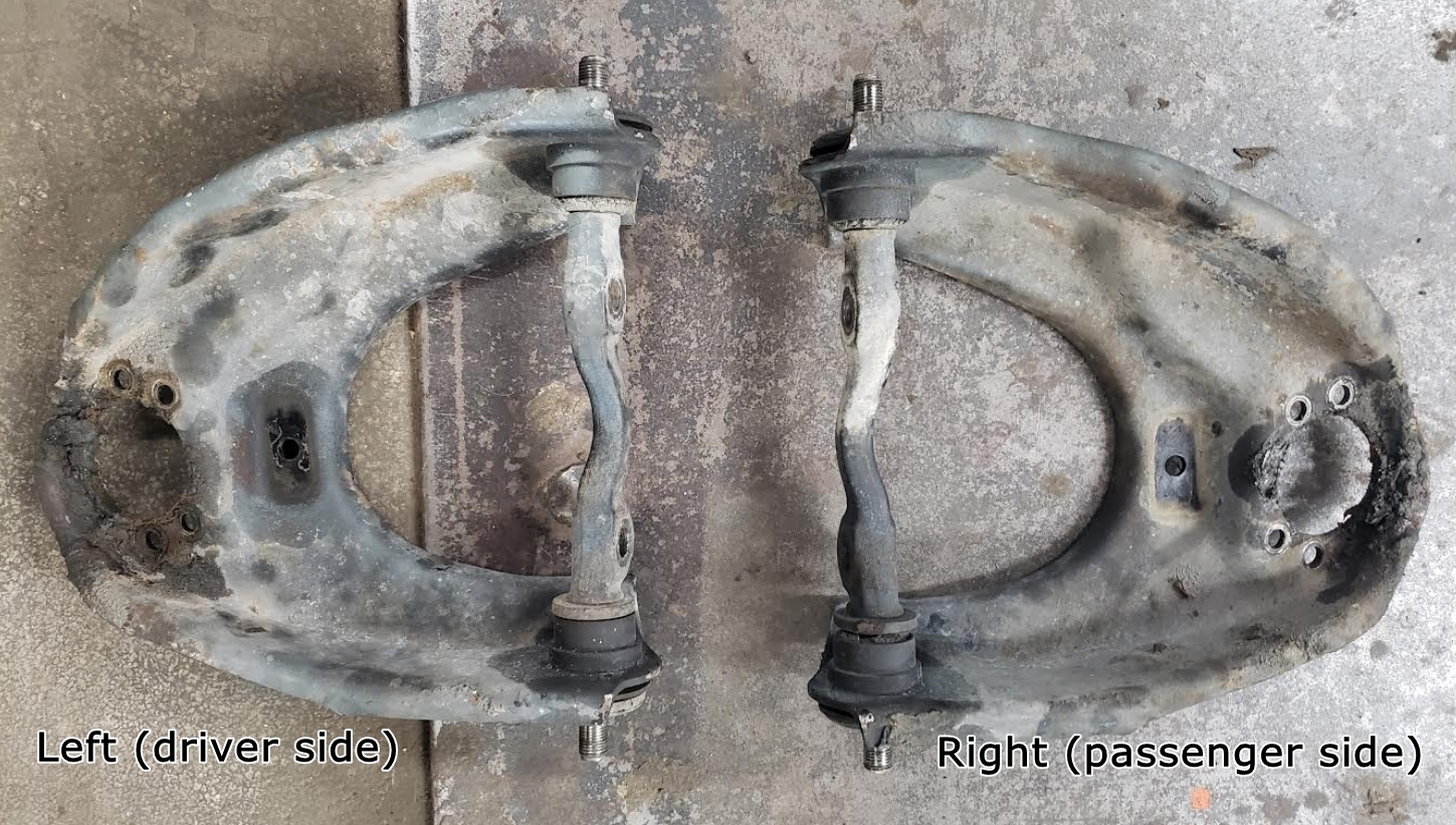
another shot of the upper arms before the bushings are pulled - hopefully enough to re-assemble them in the correct positions.
In reply to oldeskewltoy :
Yes, just the amount you need to - it should be fine and it would be a lot quicker. If you decide/see later that you need to reinforce it, you can. But I bet it will be fine. Maybe weld in a rib along your cut line to continue the existing edges
Those upper ball joints look so much like GM G/S chassis upper ball joint bolt pattern that it isn't funny. (G-body: '81-87 midsize RWD, S-chassis: S10 2wd pickups and Blazers, which are like narrowed G-bodies in the front)
It's probably a case of coincidental evolution.
You'll need to log in to post.