There are many things the 4AG and the 7MG share.... unfortunately for this test...... cylinder bore isn't one of them

thank you gentlemen....... 
7MG has a bore of 83mm, this one will have an 84mm bore...... my flowbench has an 81mm bore....... 
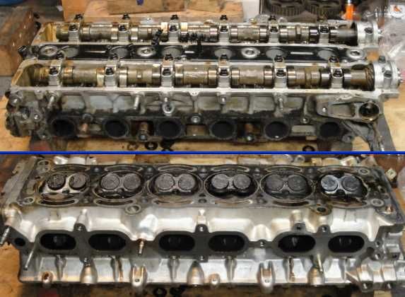
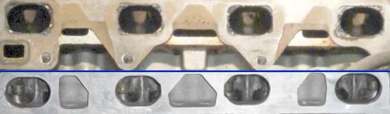
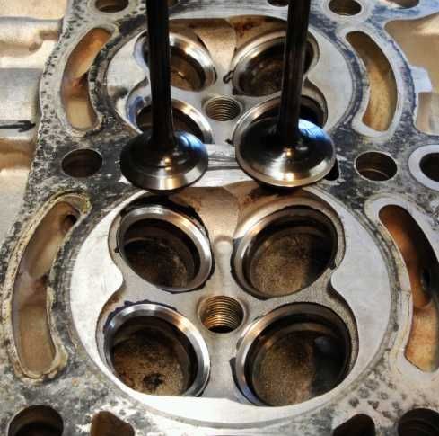
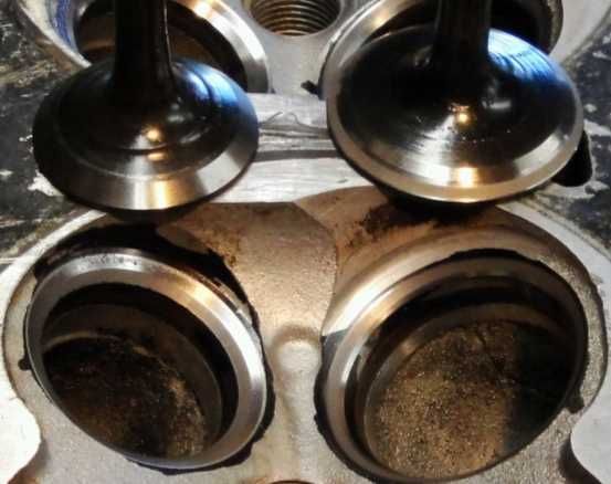
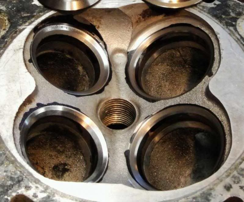
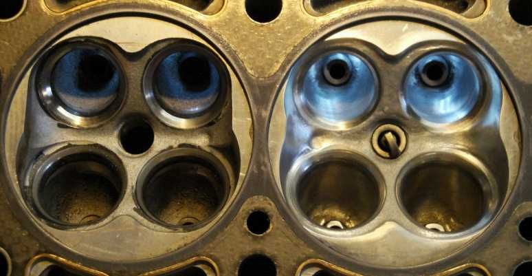
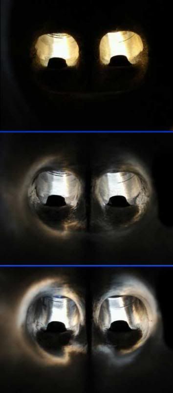
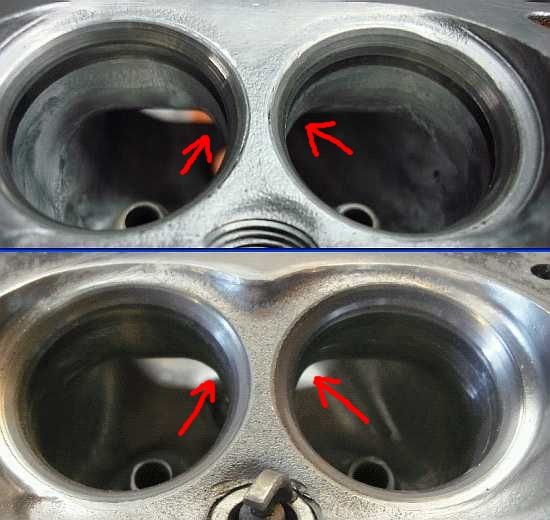
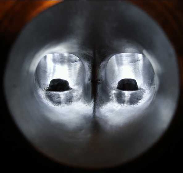
Here... for those who don't understand.... below is a 2 panel...
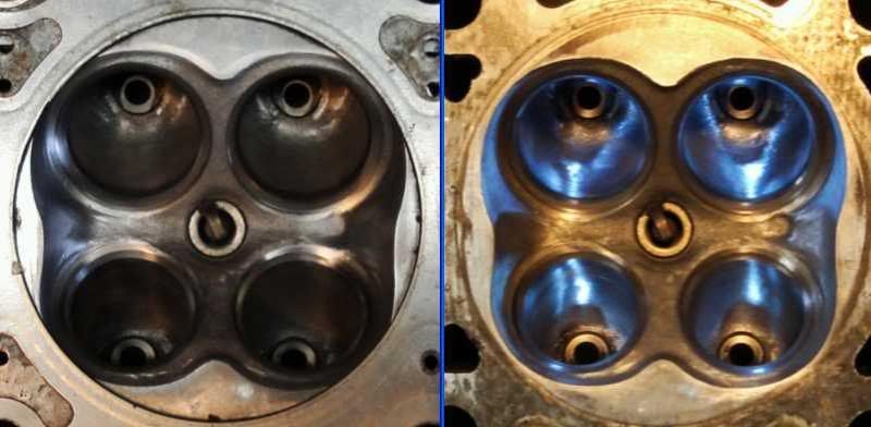
the right view is the combustion chamber ported out to 83mm, the left view is showing a 4AG gasket centered, overlayed on the 7MG - note how the gasket cuts the corners, how close the gasket is to the outer edges of the valves... now remember the 4AG gasket is 82mm... my bench is another millemeter narrower
There is no way my numbers are accurate.... because well over 10% of the valves are buried behind an 81mm flowbench bore
I still have numbers mind you... but I'll show the pretty pictures first..... :)
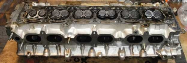
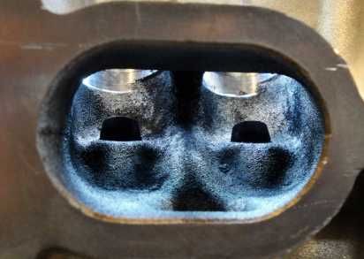
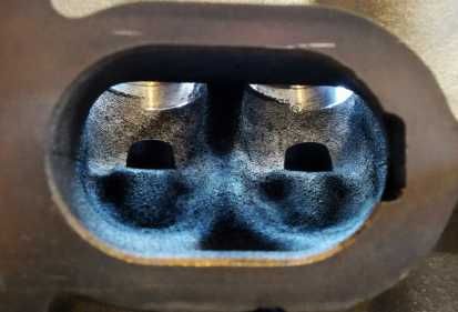
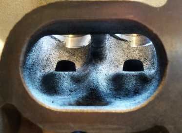
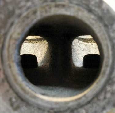
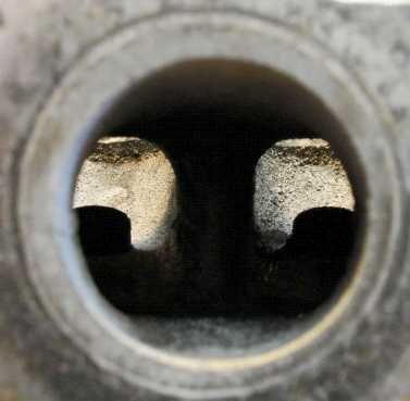
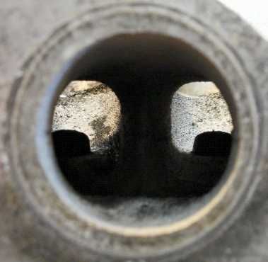
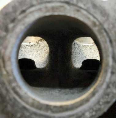
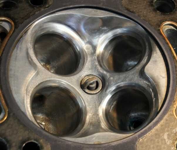
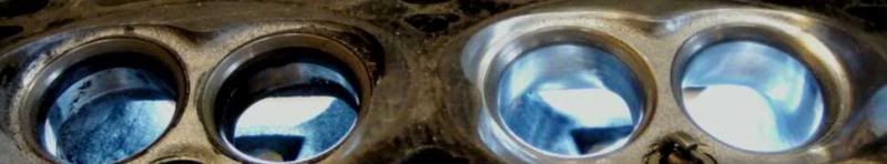
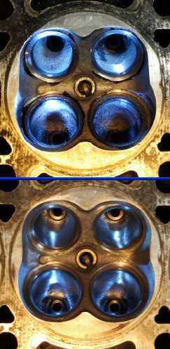
The combustion chamber retains its original configuration, I've tapered all the valve shrouding to allow for improved cylinder filling.
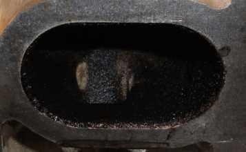
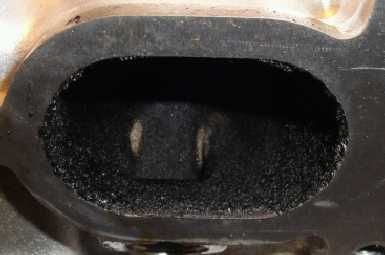
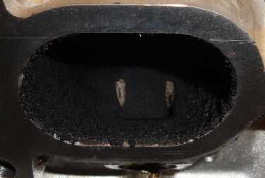
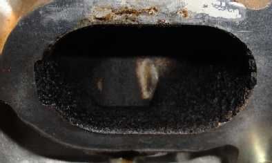
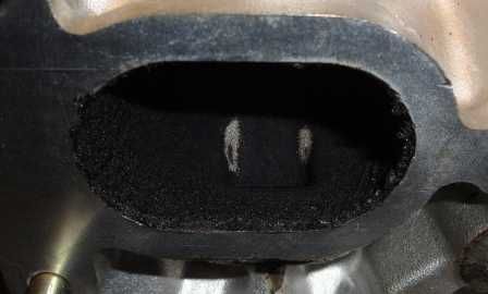
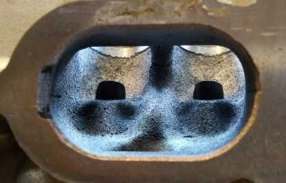
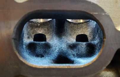
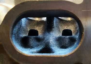
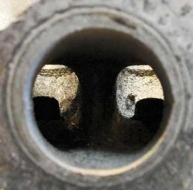
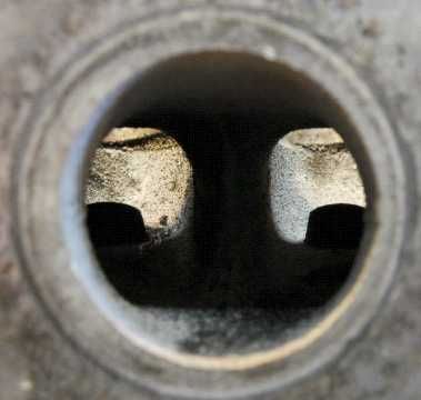
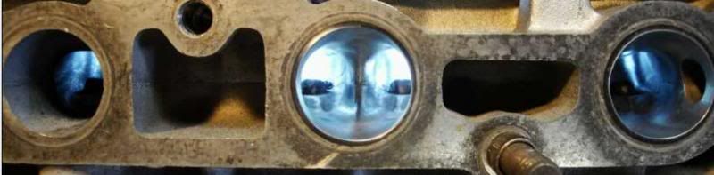
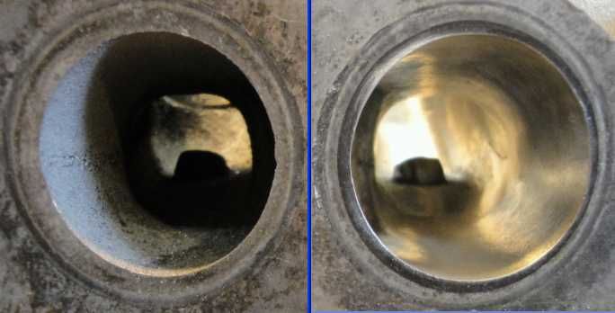
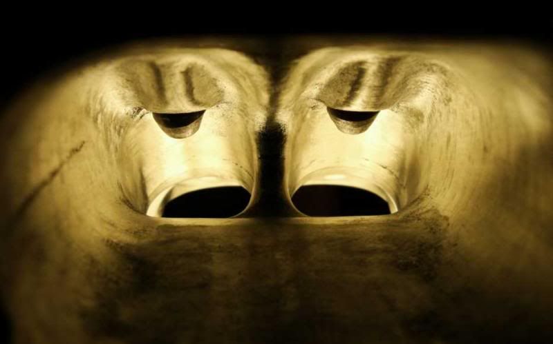
let me introduce to you exhaust port #5....
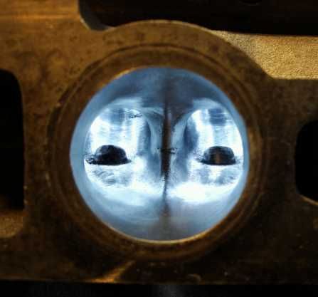
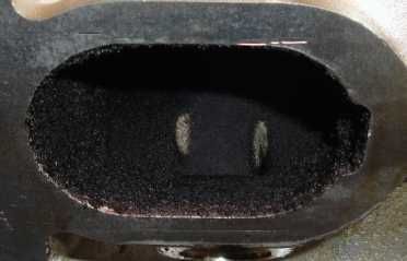
and a slightly deeper view......
I promised some numbers....
Intake:
Before cleaning.... .10 - 73.83, .15 - 107.50, .20 - 135.85, .25 - 155.95, .30 - 166.40
After cleaning..... .10 - 75.73, .15 - 111.48, .20 - 141.57, .25 - 163.67, .30 - 176.37
After 3 angle..... .10 - 79.42, .15 - 113.57, .20 - 144.88, .25 - 166.91, .30 - 179.37
After porting..... .10 - 79.32, .15 - 115.20, .20 - 146.32, .25 - 170.10, .30 - 182.74
Exhaust:
Before cleaning... .10 - 64.10, .15 - 95.97, .20 - 113.73, .25 - 124.32, .30 - 129.58
After cleaning..... .10 - 64.00, .15 - 95.20, .20 - 115.30, .25 - 125.80, .30 - 130.80
After 3 angle...... .10 - 64.15, .15 - 95.90, .20 - 114.91, .25 - 126.62, .30 - 132.60
After porting...... .10 - 64.20, .15 - 95.35, .20 - 115.84, .25 - 127.70, .30 - 135.60
Now just 5 more to go....... 


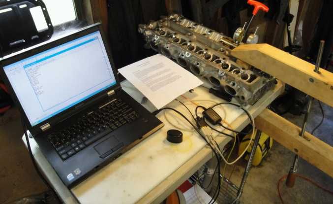
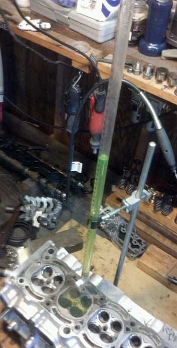
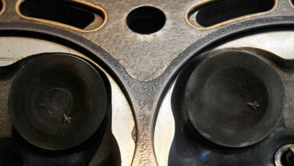
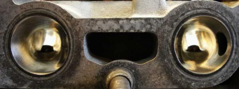
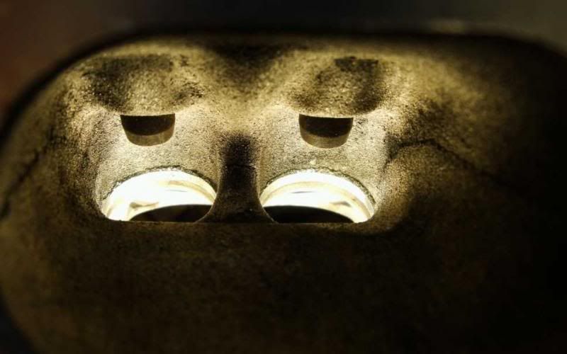
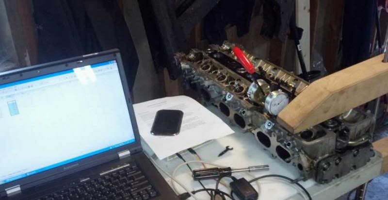 checking the intake side...
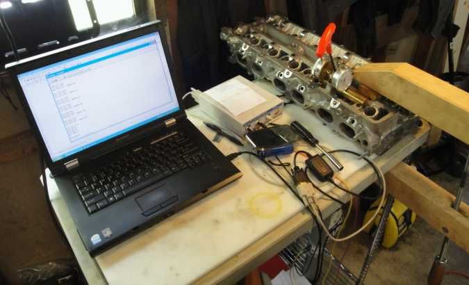
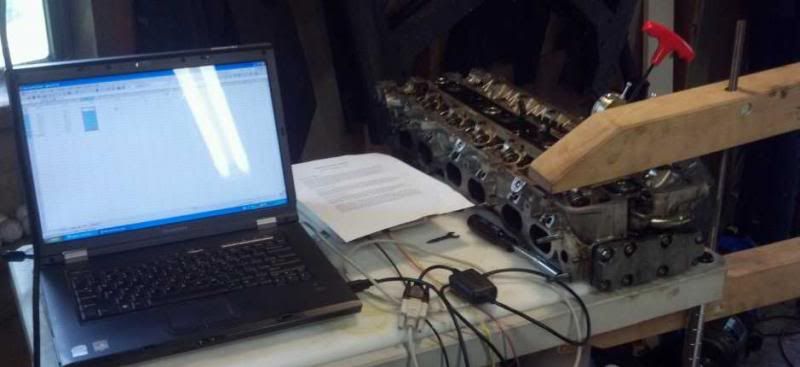 and the exhaust side...