1 2
nocones
nocones GRM+ Memberand PowerDork
12/21/22 11:21 a.m.

I am involved in a challenge car effort that is having it's suspension reworked.  The car is ~800lbs, small, Motorcycle Engined, and is built on a F500 chassis..   Ok It's FDAT.   

We are converting the Solid rear axle to utilize a differential and uprights from a Chevrolet Cobalt.  We've looked and explored several different options for suspension layout and keep coming back to keeping it simple.  We've explored DeDion (with various 4/3/truckarm linkages), Dual A-arm, pure Trailing Arm, putting shocks on the existing setup and have settled on the most straight forward best compromise design being a semi-trailing arm with inclined bushings.

There are lots of stories of horrors of semi trailing arm designs, but there are also lots of successful cars that use them.  2nd Gen RX7's, E30 BMW's, Many Mercedes, Datsun 510's, Porsche 911/914/944. Yes some of those vehicles have some additional linkages to correct camber or toe behavior, and most STA designs have morphed into to the modern 5 link suspenison, but it seems like it would work well for this application.

We have some typically GRM methods for how we are going to accomplish the pivots and overall arm engineering that we will do during the next BDT build day covered in the FDAT thread, but I wanted to make a separate thread to discuss the Design aspects for STA.   

I'm very familiar with design of a Dual A-arm, and have experience evaluating various linkages for traditional solid axles but I've never attempted to do a STA.   Which means I'm not very familiar with what the sweet spot of compromise is.  

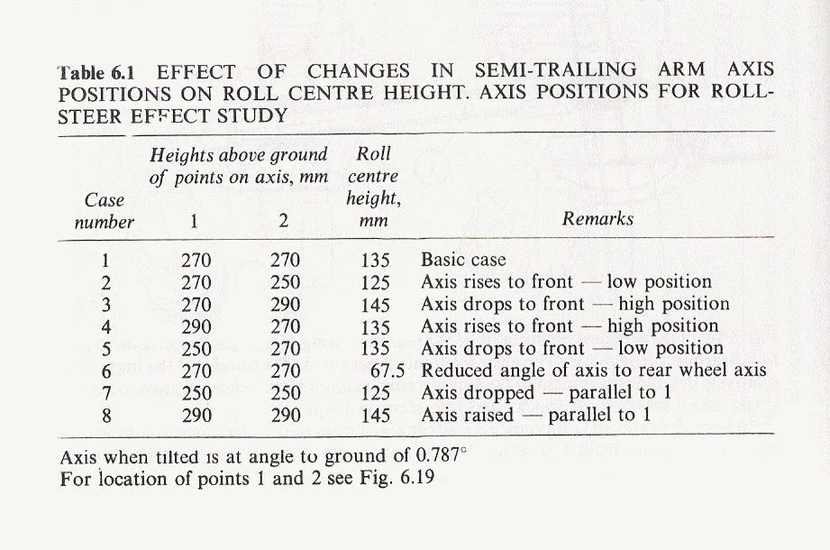
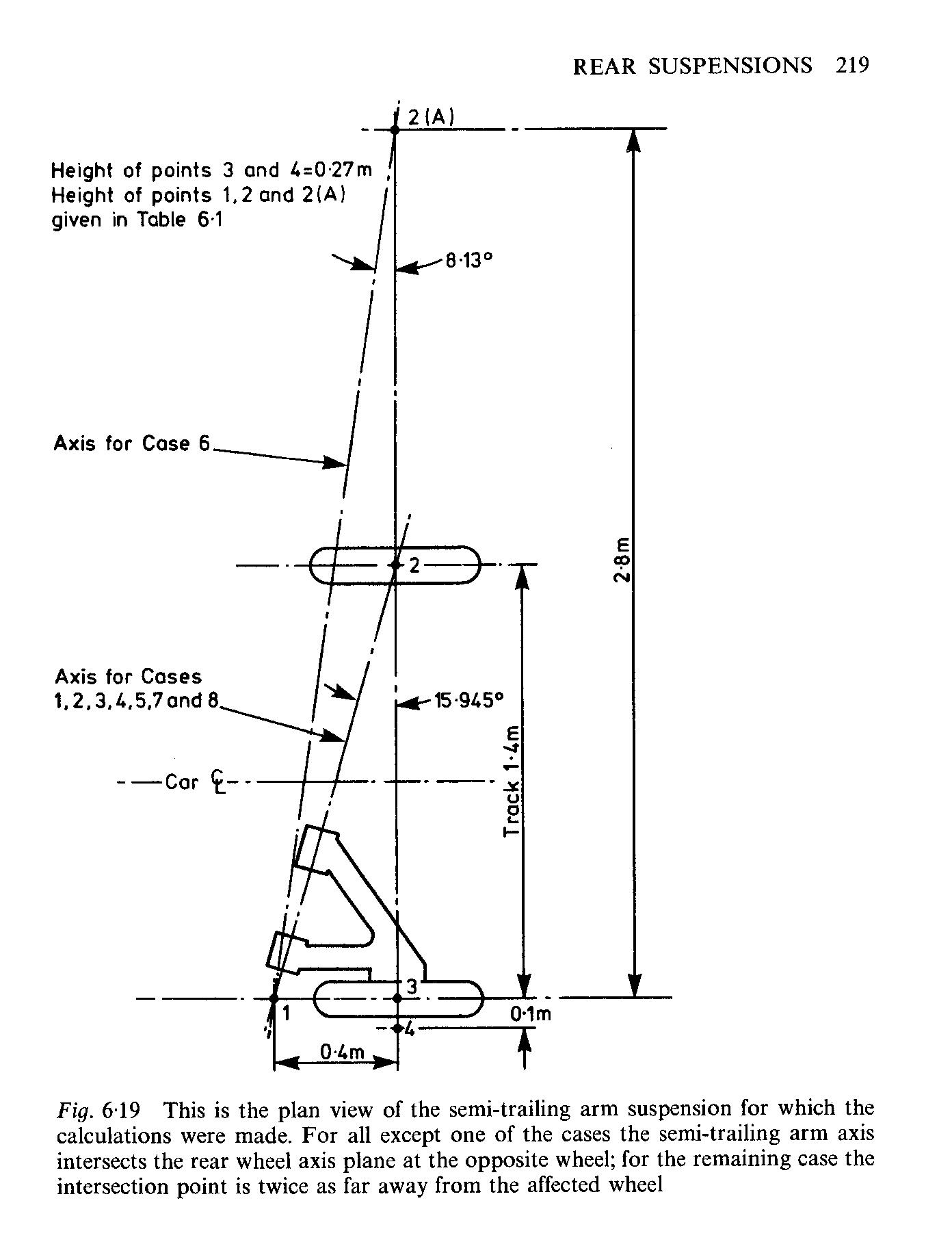
Design considerations seem to be focused on the front and Top view angle that the STA pivots.  The intersection of A line extended through the two bushings and the Axle centerline defines the Instant center which then can be evaluated for Camber Curve (Top View) and Roll Center height (front View).   

This is basic stuff with common tradeoff analogs with Dual A-arm.  I would traditionally for a Rear suspension run a IC of ~1 x Track Width to give some reasonably agressive roll camber curve while not having excessive weight jacking that can occur with very short instant centers.   Roll Center I would target ~30% of anticipated CG height because I love avoiding swaybars if possible for cars with stiffer (2.0+Hz ride frequencies).  

But.. the STA introduces other concerns that I am not as familiar with.  Toe change with bump and roll is one but what other dragons are out there? 

FDAT has pillowy soft 10" Full Bias Ply slicks that are not super sensitive to camber/toe.  It is also hilariously light with each rear corner only weighing approximately 200lbs.  We will build around a stiffer ride freuqency but not as stiff as a would be typical with a full Aero car, so there will be some movement of the suspension.   Assume we are looking at around 1" bump/droop, which for a TW of 48" is not super small motion.  The STA arms themselves will be about 27" in length because of the layout of the car, so that will go some way towards reducing some of the rotation they experience simply because they will be long.  

If you've owned a STA car or done setup and design please discuss some of what you've experienced.   As always with my suspension designs my goals are linear feedback and being "drivable" above absolute knife edge grip, so understanding the parameters that effect the STA design better will help achieve that goal.   And hopefully we can educate other people along the way.  

dps214
dps214 Dork
12/21/22 12:12 p.m.

I don't know much about the theory (interested to learn more though) but have a decent amount of real life experience. If you look at some photos, the 944 setup has the pivot points nearly horizontal and also not a ton of fore-aft separation. The result of that seems to be almost no toe change with roll, but also not a ton of camber gain and a lot of squat under acceleration. If you want stability over all else, that's probably the way to go. I also briefly owned a Z3 m roadster. It was definitely less stable, but also worked surprisingly well as long as you had the confidence to exit every corner with 5-10* of slip angle.

Robbie (Forum Supporter)
Robbie (Forum Supporter) MegaDork
12/21/22 1:42 p.m.

Iirc from my e36 days, the problematic toe change comes from worn out bushings rather than the geometry. Specifically on the e36 that is side to side movement of the front trailing arm bushing, but that might not be relevant because e36 is probably closer to multilink than semi trailing arm design. 

Robbie (Forum Supporter)
Robbie (Forum Supporter) MegaDork
12/21/22 2:14 p.m.

How is antisquat calculated/adjusted?

nocones
nocones GRM+ Memberand PowerDork
12/21/22 3:25 p.m.

In reply to Robbie (Forum Supporter) :

I am not sure but It would make sense that it was evaluated by the line through the contact patch and the pivot bushings.    That's the line the force will take into the chassis.  So the height of the bushings will come into play and the length of the arm will impact how quickly it changes with bump/droop.   

I will attempt to make some Google sheets that do math for us on this. 

maschinenbau
maschinenbau GRM+ Memberand UberDork
12/21/22 4:18 p.m.

I think with only an inch or two of travel I would keep alignment consistent and make it as easy to build as possible. Horizontal and colinear pivot axes would be my vote.

I would start with the parts you have. I assume you need to reuse the Cobalt knuckle so you can keep the axles. That means you have a knuckle that wants a strut and two ball joint. It may be difficult to adapt trailing arms to that knuckle, unless the hub is removable and you can fab a new housing for it. What was the plan there? Is a strut suspension to big to fit this lil car?

Robbie (Forum Supporter)
Robbie (Forum Supporter) MegaDork
12/21/22 4:26 p.m.

In reply to maschinenbau :

The hub bolts on to the strut in the cobalt, which makes for a convenient way to attach these hubs to whatever we build.

Strut would be fine, except for the general lack of anything of substance nearby to attach the tops of the struts to. 

nocones
nocones GRM+ Memberand PowerDork
12/21/22 4:36 p.m.

In reply to maschinenbau :

We do not posses the cobalt arms.  We are going to anchor the trailing arms to the strut bolts and utilize the Brake caliper bolts for additional strength.   The bearings are removeable but the Cobalt uprights are Aluminium so we think we can make a simple pair of flanges on our trailing arm easier then an entire steel housing to hold the bearings.   We are going to run a Diff Mounted center brake on the car and live with the potential minor loss of braking if 1 wheel is in the air.  

So by Horizontal and Colinear do you mean basically a full Trailing arm?  We had considered that and didn't have a great reason to not do it other then the poor camber performance.  Roll center height would just be the height of the pivots in that situation.  

Driven5
Driven5 UberDork
12/21/22 4:51 p.m.

Front view instant center: Determined by point where pivot axis crosses lateral tire center-plane.

Roll center: Determined as usual between longitudinal tire center-plane and front view instant center.

Side view instant center: Determined by point where pivot axis crosses the longitudinal tire center-plane.

Typical Anti-squat: Determined as usual for IRS between tire rotational axis and side view instant center. See "b" below.

Chain-drive instant center: Determined by convergence between driven side of chain and side view instant center.

Chain-drive anti-squat: Determined as usual for live axle between tire contact patch center and chain-drive instant center. See 'd' below.


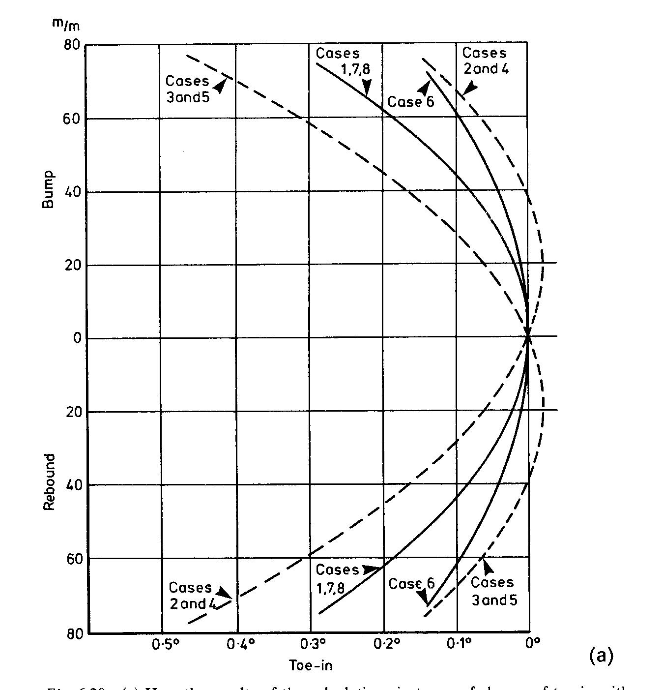
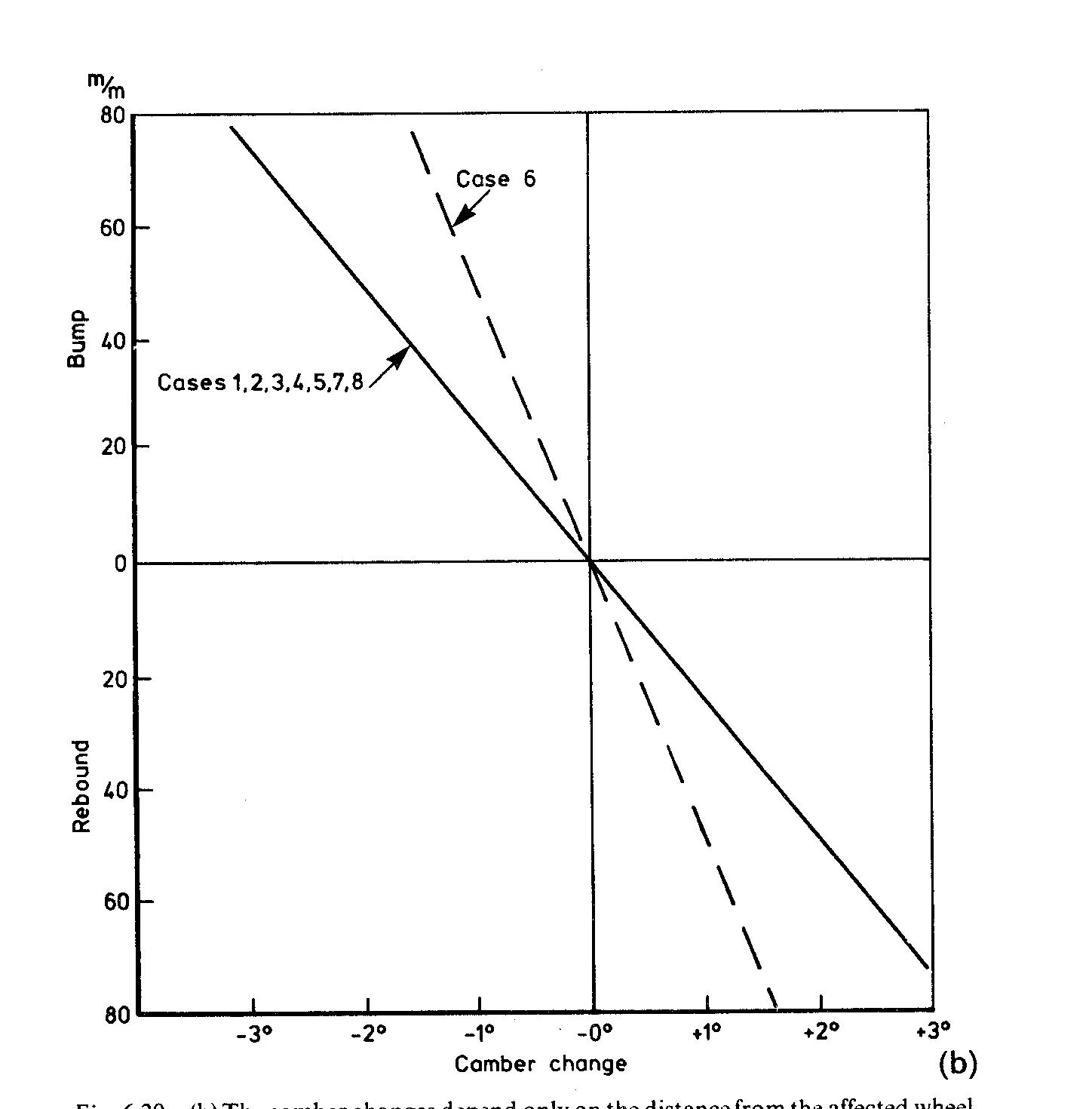
Camber gain: Determined entirely by top view angle of pivot axis.

Toe curve width: Determined entirely by top view angle of pivot axis.

Location along toe curve: Determined entirely by front view angle of pivot axis.


The toe-out concerns can come from angling the front view of the pivot axis, and bushing deflection. Production based setups and experiences may not be fully applicable to this dedicated race scenario either though.

Full disclaimer: I have zero practical experience setting up Semi-Trailing Arm suspensions.  That being said, if it were my purpose built racecar, I'd probably consider to try (as much as possible) to keep the pivot axis horizontal at the desired roll center height and just accept the pro-squat implications. Then, if desired for the drag race, perhaps something as simple as an curved tube (very stiff bump spring) that can be bolted between the two STA's to provide 'anti-squat' weight transfer effects. With the limited wheel travel your targeting, you should generally be able to keep yourself in a pretty benign part of the toe curve. Beyond that, it's largely determining how much camber gain you need/want against this.


Edit: Incorrect chain drive squat statement removed.

Driven5
Driven5 UberDork
12/21/22 5:03 p.m.

And I know you're looking to KISS... But since you're looking at trailing arms and other 'unconverntional' options, I'll throw this slight complication at you for consideration:


It's a trailing arm suspension that camber compensates. Also, since the anti-roll forces are loaded through the opposing suspension instead of the chassis, it produces a unique anti-jacking effect. This transverse rod suspension was designed by Torix Bennett and used on Fairthorpe TX cars.

Pete. (l33t FS)
Pete. (l33t FS) GRM+ Memberand MegaDork
12/21/22 5:59 p.m.

Look at what the XR4Ti guys do about their rear arms.  There is a significant mounting axis angle to them and it causes all sorts of issues.

Mr_Asa
Mr_Asa UltimaDork
12/21/22 6:22 p.m.
Driven5 said:

And I know you're looking to KISS... But since you're looking at trailing arms and other 'unconverntional' options, I'll throw this slight complication at you for consideration:


It's a trailing arm that camber compensates. Also, since the jacking forces are loaded into the opposing suspension instead of the chassis, it produces an anti-jacking effect.

Nice.  Looks like it might be somewhat easy to implement as well.

maschinenbau
maschinenbau GRM+ Memberand UberDork
12/21/22 6:27 p.m.

In reply to nocones :

Yep just a regular trailing arm. Just build in some static camber adjustment where the hubs attach to the arms and KISS. Although I very much like that transverse rod setup.

JoeTR6
JoeTR6 Dork
12/21/22 7:15 p.m.

The semi-trailing arm setup on a TR6 can work pretty well, but there are trade-offs.  To limit the squat, we put in stiff and then stiffer rear springs.  This helped, but adding a rear sway bar caused the inside rear wheel to lift in a corner, so it was adjusted softer until the front wheel tended to lift first.  A limited-slip diff helped quite a bit.  Later apexes and getting on the throttle early worked best for me with this setup.

Driven5
Driven5 UberDork
12/21/22 7:16 p.m.
nocones said:

We do not Roll center height would just be the height of the pivots in that situation.  

I thought RC on a pure trailing arm was effectively at ground level, due to the IC being at infinity.

Pete. (l33t FS)
Pete. (l33t FS) GRM+ Memberand MegaDork
12/21/22 7:23 p.m.

In reply to Driven5 :

THAT depends on the angle it's mounted at.  If it is a straight line across so track width does not change with suspension motion, yes.

VW/Corvair swingaxle suspensions are essentially trailing arms with one pivot at the suspension arm pivot and the other pivot at the axle joint.  They decidedly do not have a roll center at ground level, and it moves around quite a lot, as people discover when braking into a corner and the roll center goes higher than the car's center of gravity.


Going to an "IRS" fixed that by lessening the angle of the effective trailing arms' axis of motion.


BMW have a much less aggressive pivot angle compared to XR4Tis, which is why I brought them up.

Driven5
Driven5 UberDork
12/21/22 8:00 p.m.

In reply to Pete. (l33t FS) :

Hence all of the specific contextual references to "horizontal and colinear" pivot axis, "full" trailing arm, and "pure" trailing arm for that part of the discussion.

Streetwiseguy
Streetwiseguy MegaDork
12/21/22 8:07 p.m.

I forget who it was that was very successful in ITA with a twist beam Sentra.  1000 pound per inch springs in the rear. 

" Any suspension design works if you don't let it move."

wvumtnbkr
wvumtnbkr GRM+ Memberand PowerDork
12/21/22 8:13 p.m.

I didn't read all the responses,  but I have road Raced an rx7 and an e30.  The designs are very similar with a few added links on the rx7 to do passive toe control.  First step I did was eliminate the passive toe control.


My advice is to not let the suspension move too much and anything will work.


This car is light and doesn't need much travel.  


From my experience with both cars, decent dampening and light springs gives tremendous rear end grip.


I'm not sure it helps with the design, but kiss most likely applies here.

Robbie (Forum Supporter)
Robbie (Forum Supporter) MegaDork
1/8/23 9:00 p.m.
Driven5 said:

Front view instant center: Determined by point where pivot axis crosses lateral tire center-plane.

Roll center: Determined as usual between longitudinal tire center-plane and front view instant center.

Side view instant center: Determined by point where pivot axis crosses the longitudinal tire center-plane.

Typical Anti-squat: Determined as usual for IRS between tire rotational axis and side view instant center. See "b" below.

Chain-drive instant center: Determined by convergence between driven side of chain and side view instant center.

Chain-drive anti-squat: Determined as usual for live axle between tire contact patch center and chain-drive instant center. See 'd' below.


Camber gain: Determined entirely by top view angle of pivot axis.

Toe curve width: Determined entirely by top view angle of pivot axis.

Location along toe curve: Determined entirely by front view angle of pivot axis.


The toe-out concerns can come from angling the front view of the pivot axis, and bushing deflection. Production based setups and experiences may not be fully applicable to this dedicated race scenario either though.

Full disclaimer: I have zero practical experience setting up Semi-Trailing Arm suspensions.  That being said, if it were my purpose built racecar, I'd probably consider to try (as much as possible) to keep the pivot axis horizontal at the desired roll center height and just accept the pro-squat implications. If possible, get the chain drive converging with the side view swing arm in a way that helps reduce the pro-squat rather than making it worse. Then, if desired for the drag race, perhaps something as simple as an curved tube (very stiff bump spring) that can be bolted between the two STA's to provide 'anti-squat' weight transfer effects. With the limited wheel travel your targeting, you should generally be able to keep yourself in a pretty benign part of the toe curve. Beyond that, it's largely determining how much camber gain you need/want against this.

Can we talk about the chain drive anti squat a bit more?

My big concern right now is that basically all my semi trailing arm designs end up with pretty severe "pro squat", which I'd like to avoid. This is because the major frame members I have easily available to mount the trailing arm to are close to ground level (below the axle level). 

The engine is also mounted in such a way that while it is as low to the ground as reasonable, the chain drive sprocket is higher than the axle sprocket.

If Im reading (b) right, I think this means my n line will be behind the axle, indicating very severe pro squat. 

Am I reading that right?

irish44j (Forum Supporter)
irish44j (Forum Supporter) MegaDork
1/8/23 9:10 p.m.
dps214 said:

I don't know much about the theory (interested to learn more though) but have a decent amount of real life experience. If you look at some photos, the 944 setup has the pivot points nearly horizontal and also not a ton of fore-aft separation. The result of that seems to be almost no toe change with roll, but also not a ton of camber gain and a lot of squat under acceleration. If you want stability over all else, that's probably the way to go. I also briefly owned a Z3 m roadster. It was definitely less stable, but also worked surprisingly well as long as you had the confidence to exit every corner with 5-10* of slip angle.

I always assumed the squat of the 944 setup was due to the torsion rod spring setup, that seems to have a lot less stiffness at the beginning of its travel (especially when at the forward end of the trailing arm) compared to a conventional spring setup further back on the arm (like in an e30/z3).

Driven5
Driven5 UberDork
1/9/23 2:05 a.m.
Robbie (Forum Supporter) said:

Can we talk about the chain drive anti squat a bit more?

My big concern right now is that basically all my semi trailing arm designs end up with pretty severe "pro squat", which I'd like to avoid. This is because the major frame members I have easily available to mount the trailing arm to are close to ground level (below the axle level). 

The engine is also mounted in such a way that while it is as low to the ground as reasonable, the chain drive sprocket is higher than the axle sprocket.

If Im reading (b) right, I think this means my n line will be behind the axle, indicating very severe pro squat. 

Am I reading that right?

My apologies. Taking a second look at this, I realize that I was mistaken when thinking about your chain driven swing arm proposal. While the chain drive (d) pro/anti-squat would apply to an F500 style axle, once the differential is chassis mounted, the forces on the suspension no longer care about how it's being driven and the chain drive itself becomes irrelevant. So it reverts to a simple 'inboard drive' (b) at that point.

This is good news for you, as that means you go from what would have been tragically bad pro-squat, as you figured out, to just 'run of the mill' bad pro-squat. It will simply be the angle of the line between your wheel center and your side view instant center of the semi-trailing arm pivot axis. 

nocones
nocones GRM+ Memberand PowerDork
1/11/23 1:25 a.m.

Ok I fell into a hole.  My brain hurts, but I think I've made a google sheet that simulates a swing axle rear suspension.  

Ploting the intersections and figuring out pivot geometry is "easy".  Except Google Sheets is not as flexible as MS Exel for making charts.  To make a XY chart in Google sheets each "series" has to be a different column, BUT different columns cannot reference the same "X" values they have to have their own X values, so your Chart data input ends up with this silly waterfall look.

which makes this chart
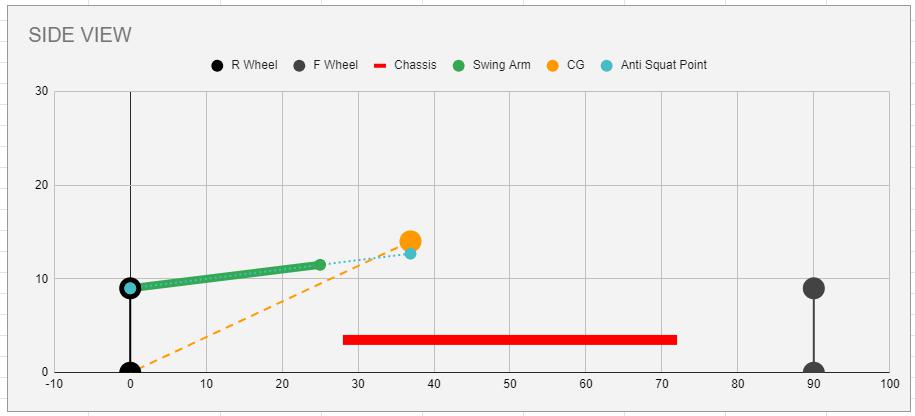
It took me a while to get my arms around "Anti-squat". I will start with this is my understanding and I easily can be wrong (Same thing with all the math in this spreadsheet).  If you figure out that I am please tell me.  

I will try to draw something to communicate but this chart does a decent job.   So Imagine that we are accelerating the car.  Lets assume for a minute that the car is a rigid body with no suspension.  The rear tire pushes on the ground and the ground pushes back.  This force acts on the vehicle CG through the orange line.  This force from the ground through the orange line has both a horizontal and vertical component because it is a vector at an angle from the tire to the CG.  The CG acts on the rear tires along this vector in the direction opposite the acceleration.  As this is the rear tire of our vehicle Horsepower makes us go Right, and the CG tries to move left pushing back with traditional F=MA acceleration, but also DOWN at a magnitude determined entirely by the geometry of the vehicle.   This downward force is ONLY due to acceleration, and it is in addition to the static force the CG applies due to gravity.   In a fully rigid car (Say FDAT 2020) this doesn't matter, this force just goes into stress in the chassis along the orange line (remember car is rigid) and the vertical force UP from the ground perfectly balances the DOWN from the CG.  

Ok so now our vehicle has suspension.  This downward force caused by Acceleration acts on the suspension.  We have to think about the forces in the chassis in 2 ways; 1. The force the CG imparts on the ground (This force is along the Orange line with Horizontal and vertical components); 2. The force the suspension imparts on the CG.  This force has to EQUAL the force along the Orange line, however the way the suspension imparts it on the chassis is a function of geometry.  

This is where the n line from Driven5s charts plays a roll.  If we could have our suspension impart a equal UPWARD force that matches the downward force due to acceleration WITHOUT using the springs we could have a rear suspension that would not compress on acceleration.  By orienting the suspension linkages to ensure that the force from the wheels (Through the Green line on the chart) matches the angle of the orange line we could make this happen.  Different suspension types handle this differently with the biggest difference being how the torque driving the wheels is reacted.  For chassis mounted differentials (Dual A-arm IRS, Swing axle, DeDion, Transaxle, Multilink) there is no torque loading into the suspension.  The force from the ground acts on the suspension at the wheel bearing.    For vehicles with suspension mounted differentials (Solid axles with any kind of linkage) the torque reaction results in the force coming into the chassis at the ground.  

Look back at our chart.  For a swing axle this means that that Green line would have to be parallel to the Orange line to get to an equivalent upward force.  In fact that is exactly what 100% anti squat is.   

So in the chart you can see that the green line is in fact not parallel to the orange, so we do not have 100% antisquat.  By math we have approximately 25%, which means that 25% of the downward force due to acceleration is reacted by the upward force from the swing arm.  The remaining 75% has to be balanced so it would go into compression on the springs.   If the forward pivot was lower such that the green line was Horizontal we would have 0% antisquat and 100% of the downward force would go into the springs.  You can imagine if the swing arm pivot was BELLOW the hub and therefore declined the suspension would introduce a DOWNWARD force on the chassis, which would be called "Pro-Squat" and would result in a >100% force being sent to the springs.  

As an aside solid axles are crazy superior to IRS for "squat" geometry.  Since the force comes along the ground through the "Virtual Swing Arm" instant center a 4 link or Multi link Solid axle can have 100% anti squat and still have a very low Instant center.   A IRS design always winds up with a very high instant center, which results in other bad compromises for handling so antisquat use is limited.   

Ok so I rambled a lot and I haven't even gotten to the rest of the sheet.  

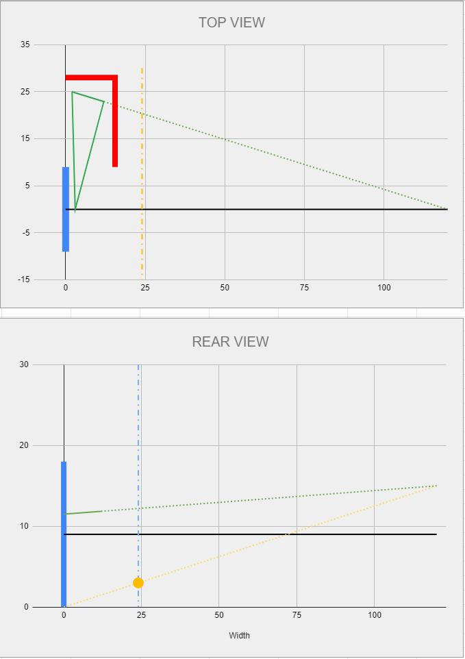
Using very basic geometry I layed out the Top and Rear view of the swing arm to figure out where the pivots would be.  These are entirely based on inputs that set up the geometry.  I selected the outer swing arm pivot height/width and position along the wheelbase.  The desired VSAL length is selected and roll center height, and the spreadsheet calculates and plots the geometry, picking the inboard pivots and I get these charts.
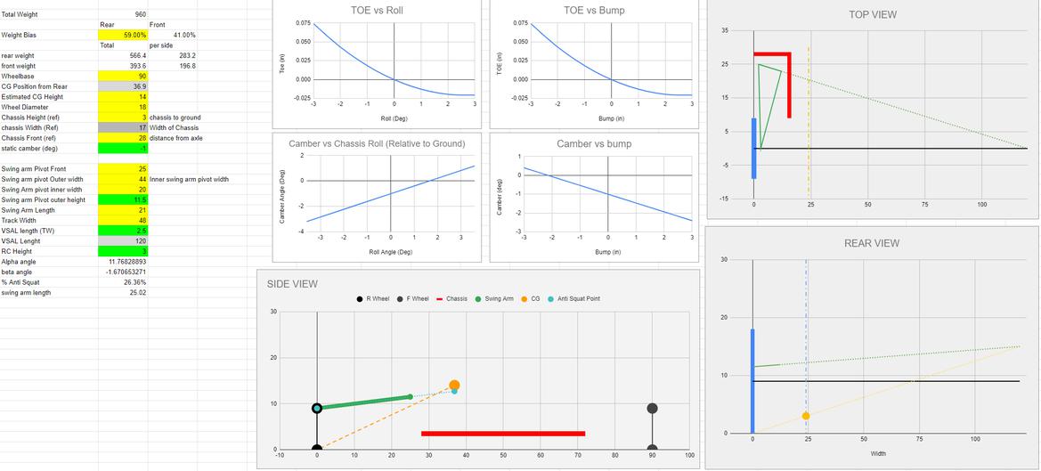
This is what the overall sheet looks like
The next step was the hard part that I spent way to much time over the past 3-4 days working on.  Looking at the Top and Rear view you see that the swing arm is not perpendicular to the car in either view.  I called these angles Alpha and Beta and they are super annoying and I hate them.  Determining the side view geometry and anti squat is the easy part.  Beyond that it got wierd and I probably made errors.

I was primarily interested in evaluating camber/toe.  I know that Susprog3D can do this.  I don't own it.  I can't validate how they did their calculations.  I searched for a different free alternative and I couldn't find one so I made one.  I initially tried the calculations shown on the following link: http://www.e30sport.net/tech_articles/susp-tech/rear_curves/index.htm

This gentleman did a good amount of work and produced formulas that consider the top view angle (frustratingly I called it Alpha and swingarm rotation Theta and he used them backwards) which for an E30 are apparently 12-15 deg.  His camber equation worked fine.  I modified it to include the "beta" angle from the rear view.  A3 is Swing arm Displacement, F1 is the Alpha angle, H1 is Beta.   

This equation produces logical results for camber for Alpha angles from 0-90 degrees and for Beta angles from 0-90 degrees.   

So camber was settled (ish, again more at the end).  Then it was time for Toe and it was horrible. The simple equation in the E30 evaluation did not work.  If I set the alpha angle to 0 or 90 it did not produce logical results.  It may of done a fine job estimating at 15 degrees but I wanted flexibility. 

I'm not going to attempt to explain in detail how I developed the equation.  Eventually I will re-draw my geometry that led to it's development but it's basic geometry.   The basics of the Toe equation is that as the arm rotates the hub moves up and in.  The wheel is fixed relative to the swing arm so it rigidly rotates and intersects the pivot axis at the same point irregardless of travel when viewed from above.  Geometric evaluation can then be made comparing the "0" travel line (which is at static toe of 0) to the horizontal plane projection of the post travel line which would now be at a more open angle.  The location of this projection can be determined based on the lengths and angles and you get this doozy of an equation.. I applogize for the aweful notation here.


Here C11 is swing arm length, F11 is the Alpha angle, A16 is vertical displacement, I11 is Beta.   And then there is B22.. OH B22.  

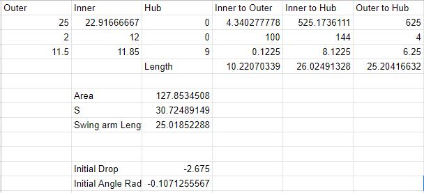
I got my equations all done and developed curves then had a realization.  The Swing arm is not level at 0 travel.  It is at completely random angles.  Sure the asumption of it being level is probably fine but I wanted more accuracy and flexibility.  So my strategy was to alter the analysis to determine the Swing Arm length from the 3D geometry of the inboard, outboard pivots and hub location.  Then from that length and the initial vertical distance from the pivots to the hub at static ride height, I could detemine the initial Theta angle that the swing arm has at rest.  This rotation angle was subtracted from the equations above and the results "zerod" to 0 travel by subtracting the 0 travel equation result from itself.  This rotation is B22.  

To calculate swing arm length I determined the length of the 3 sides of the triangle made by the swing arm using the 3D pathagorean theorem (Inner, outer, hub vertexes).  I then used Heron's formula to calculate the Aera of this triangle.  I then was able to divide 2* the area by the length of the side that represented the rotation axis.
So the bad toe equation from earlier became this:

The result of this doesn't impact camber, as camber is a very linear function for a swing arm, but for Toe it has a strange result.  Since the arm is not level at 0 ride height the result is that the curve Shifts to where 0 toe change occurs when the swing arm is level.  Since I "Zero" toe to 0 travel you can see that the toe actually has "toe in" for 2" of bump before being to have "toe out".  Roll toe is simply converting the "bump" displacement to a roll angle based on the Track width.

So that is the spreadsheet I have developed.  I used a lot of input from the forum and some google searching.  I know this is another one of my overly rambly super technical posts.  I'm sure almost no one will follow it.  I'm just hoping someone can take something away from it, if nothing other then solving frustrating problems with lots of math you forgot from highschool/college.  

I think this maybe accurate.  We will tweak on the numbers some before we build.  


For the true masochists the spreadsheet is available here.

https://docs.google.com/spreadsheets/d/16ly8wVNajQMgKwzJaJ4sKamicb4A4F7TA3pK40vOS8s/edit?usp=sharing

PLEASE FOR THE LOVE OF FSM MAKE  A COPY ON YOUR GOOGLE DRIVE.  NO this isn't the only one, I have backups.  I believe you will be able to edit if you save a copy.  I currently have it "View Only" I believe you can download it.  I have not "protected" any cells.  So It would be pretty easy to mess it up.

But, the chart inputs all auto populate as does all the calculations.  If you just deal with the colum of green/yellow texts on sheet 1 you should be able to play with it and make it work for other cars.  Different Track widths, tire diameters, swing arm pivot locations, CG's, Wheelbases all should work and give you camber/toe/antisquat.  

So I guess now is about the time we decide to do Dual A-arms or something not Semi Trailing Arms.

Driven5
Driven5 UberDork
1/11/23 3:12 a.m.

In reply to nocones :

Nicely done!

I realized that the graphs I originally linked in my first post regarding the geometric effects might not have been showing up, and have restored them as uploads. Based on that info, your charts generically seem to track. So that's at least a positive indicator on your 3D spreadsheet math. Have you tried running some of their geometry through your spreadsheet as a validation?

However, a minor correction: Since anti-squat is resisting weight transfer, the anti-squat percentage equation is weight transfer equation based. This results is the 100% anti-squat line extends to the front axle plane at CG height, not to the CG itself. In the equations below, 'l' is the wheelbase.

When you walk through the force reactions, remember that the FBD still needs to balance. So you have to account for the weight being carried by the front axle. Or thought of another way, the forces are acting through the CG as you describe, but only based on the percentage of weight carried by (transferred to) the axle.

gumby
gumby GRM+ Memberand Dork
1/11/23 7:29 a.m.

Woof, that's just.....berkeleyinBRAVO!

1 2

You'll need to log in to post.

Our Preferred Partners
tMW4jk2P4U7sjLcWu76SlxdgrHB5DM6hg2szFeCFj7HP1RoJqXttWGIi5h720tkx