Hey all, I'm redesigning an intake for my 3.8 mustang, as there's no aftermarket support, and I have a few questions about intake runner lengths and ther overall shape of the box for the upper intake.
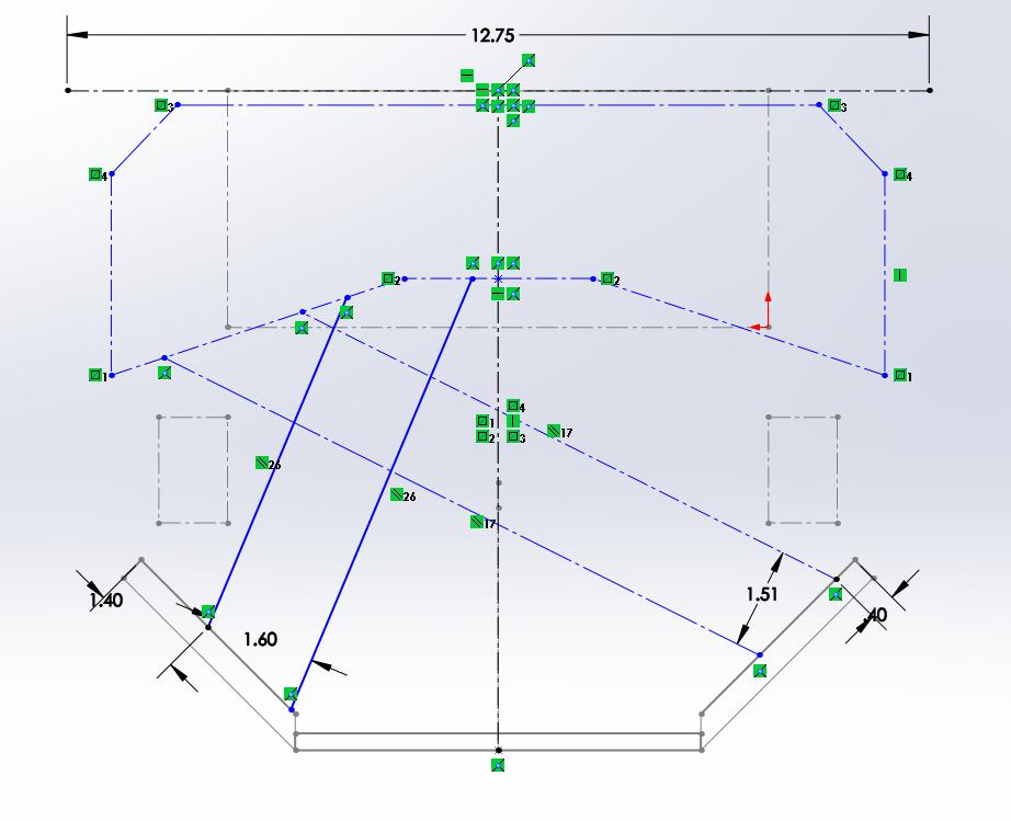
Currently, I have two design ideas, one where the runners pretty much go straight down from the V shape (first pic) and another one where the runners cross the midpoint of the engine (second pic). The runners from the first pic would be around 5.5" while the runners from the second type would be around 8". Ignore the greyed out lines, the solid blue lines are what matter
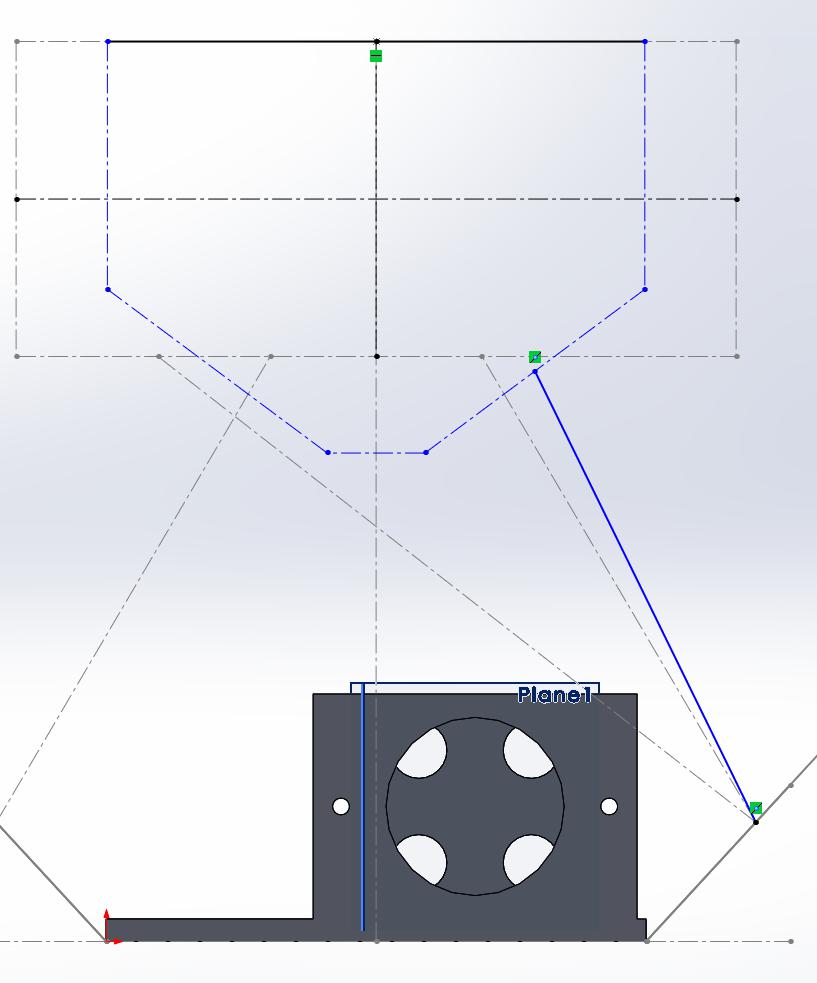
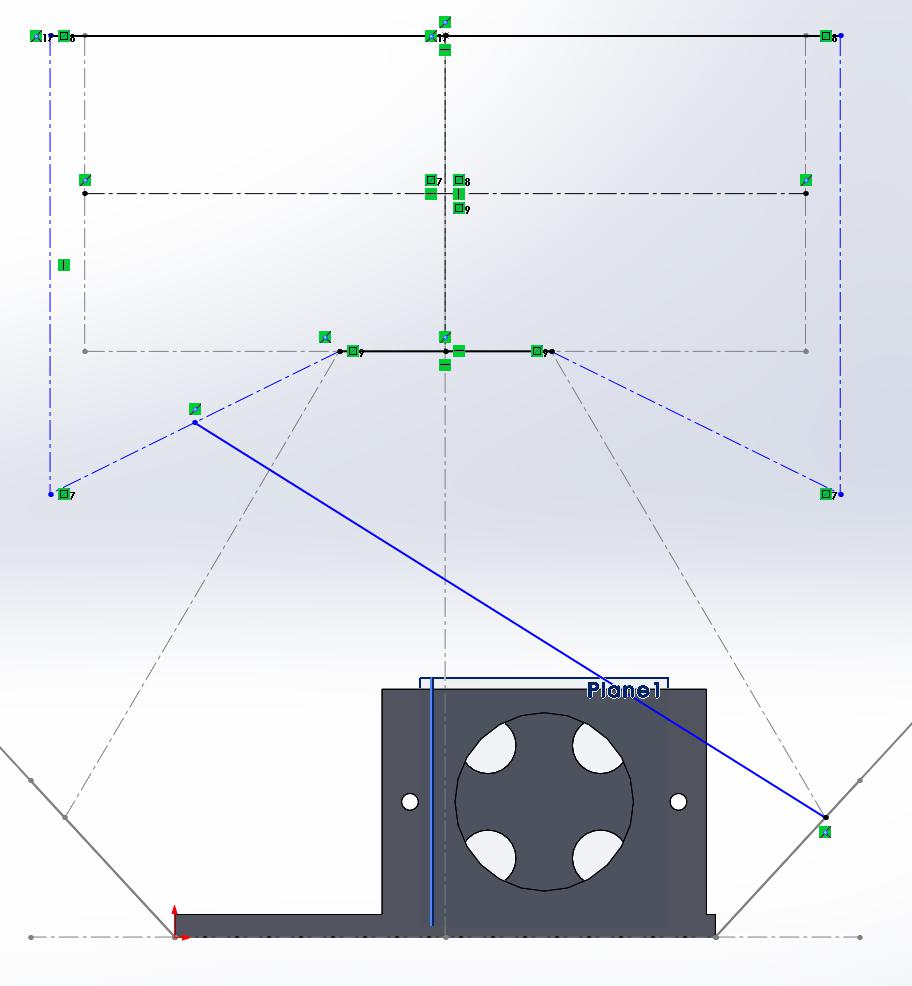
Another option I'm toying with is this engine has dual intake ports per cylinder, so I could do a short runner/long runner combo.
Let me know your thought on what's better, also if you have any suggestions. The overall goal is to improve performance as well as provide more even airflow across all cylinders.

Which design depends on the rest of your setup. Check out http://www.wallaceracing.com/Calculators.htm specifically the intake design related calculators. Be prepared to have info like your cam specs, engine specs, rpm etc handy.
Rule of thumb if you ask me is longer runner unless its something going over 8K rpm. And I'd venture a guess that on a small engine like the 3.8 a tunnel ram intake is too short a runner for ideal (maybe not, I'm used to V8 stuff). More importantly than chasing perfect runner length is making sure you have a design with good transitions (big radius) from plenum to runner. Numerous ways to do it but I've seen plenty of examples that could have been perfect length but were ruined by poor design/finished product. In your longer runner setup the available plenum is less than ideal with one side being pinched by the wall. Adding a radius to the runner to face the opening strait up while moving runner opening away from plenum wall would be an improvement. Yes the runner gets shorter but you also are making sure that there is air in the plenum that is available to the vacuum of the runners (which pulls from every direction with a proper radius).
What's your method of fabrication? That'll be the biggest limiting factor in design due to ability to achieve the end result.

I like the calculator on bgsoflex.com, it has matched some dynos I have done with intakes where you can really see the resonance. That being said resonance can be annoying if you are trying to make a broad powerband and it's why you see bikes with two short and two long stacks. That being said, lengths are from the valve to opening, so keep that in mind. Mostly you will be working on 2/3/4 harmonic as 1st on an intake like this may put it over the hood by a good bit. The short/long is interesting in a manifold that has a port per valve, you may want to stagger lengths for broadest powerband. One question is how does fuel get to both valves?
I agree on the transision being important, I have seen raised bells from plenum floor worth about a 5% bump in power all else being the same.
Often overlooked is the crossection of the runner going up at the right rate per length. There are some packaging compromises there but if you take valve area vs intake port area at the manifold per inch of port, replicating that is a good start.
I have never seen a downside from a big plenum, other than some transition tuning, where too small is easy to spot.
What is the goal you're trying to achieve with the new intake?
Would having the stock one ported or extrude honed reach those goals or desires?
Just curious.
Generally speaking longer runners are more ideal for nearly everything that isn't spinning like a sportbike or F1 engine.
Things like the dual-plenums used on many Audi race cars helps provide an even charge to each cylinder:
https://www.bufkinengineering.com/intake%20manifolds.htm
https://www.motorgeek.com/viewtopic.php?t=9470
https://www.supraforums.com/threads/dual-chamber-plenum-intake-manifolds-on-a-2jz.1119929/
Its an interesting piece of kit, not sure if it truly works without a lot of modeling and experimentation, which is not cheap or easy

Agree... goal makes all the difference. Port EFI intakes (since they don't carry fuel with the inlet air) are a lot less sensitive since they have a lot less mass.
I often point to the LT1 intake. The cam was super mild (like sub-200 degrees mild), the torque peaked under 3000, but the intake runners were about 2.5" long with a huge plenum. If you went to the effort and expense to make a custom intake that was a better match to runner length and plenum volume, it is unlikely you would change the HP/TQ numbers more than about 5 in either direction.
If you're just looking to get a functioning intake that is a performance upgrade, you kinda can't screw it up. If you're looking to hyper-tune the last 3 hp out of it, then use maths.
Calculators can sometimes lead you down an interesting path, too. I used calculators to find optimal header primary length on a Caddy 500. It was something like 6.5 feet long. In truth, if I wanted to get the last 2 lb-ft of torque, I could have built some 78" long headers, but in practice, normal headers of any kind would have been an improvement over the factory manifolds. I only mention that so you don't get discouraged trying to fit 15" runners and 5' headers only to find they don't really improve things that much.
In reply to asphalt_gundam :
The calculators are awesome, thank you for the reference! I said it was a 3.8 as that's what it was initially (and it's easier to search), the engine has been stroked and bored to 4.3l. In the intake runner and peak torque calculator page, using the optimum runner size and length calculator, it asks for the number of induction wave..I can't really figure out what's it's asking for. Do you have an idea? The method will be CNC cutting the mounting plates, sheet metal/tubes for the ports and plenum, then I have a fabricator that will be welding everything together.
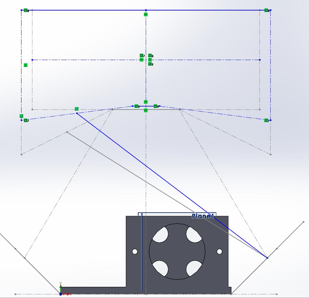
When you say to move the runner and radius it, are you saying to make it look more like this so it'll be able to pull air from more of the center than the side walls?
In reply to Stefan (Forum Supporter) :
With the new intake, I'm trying to achieve equal pressure across all cylinders, while hopefully improving flow. I already have heavily ported upper and lower intakes, but unfortunately even with that, I'm not getting even pressure and flow across both banks.
I really liked looking through the links you sent. If I can model it, I can run a flow simulation against it with Solidworks, so that'll be somewhat helpful to determine if it helps or not. I'm not sure how well I would be able to get a dual plenum to fit in this car since it's a v and not inline. I'll have to look into it further.
In reply to Paul_VR6 (Forum Supporter) :
I guess I should say the application, this is for a road race vehicle. So It'll typically be sitting in the higher RPM range (top of 6700rpm).
As for the calculator, you're referring to the "optimum intake runner calculation"? http://www.bgsoflex.com/intakeln.html
When you say the lenght is from the valve to opening, you mean to where the runner reaches the plenum or throttle body?
This car has a short/long runners but they actually share the same valve (12v engine). However, I did put oversize valves in.
I'm not sure if I fully understand where you're talking about with the right rate per length (i'm an amateur). OVerall with the runner sizes, I was trying to take the area of each port and size the runner to it (typically being oversized by 0.1")
http://www.bgsoflex.com/intakeln.html use this to play around with lengths a bit and see how the harmonics change the pressure pulses, the wallace racing one will do something similar but backward.
I would skip the dual plenum unless you have some odd packaging concerns or large flow differences on an end fed manifold with a small-ish plenum. Helpful on boosted cars with giant radiators or inner fenders you can't design around.

Curtis73 (Forum Supporter) said:
Agree... goal makes all the difference. Port EFI intakes (since they don't carry fuel with the inlet air) are a lot less sensitive since they have a lot less mass.
I often point to the LT1 intake. The cam was super mild (like sub-200 degrees mild), the torque peaked under 3000, but the intake runners were about 2.5" long with a huge plenum. If you went to the effort and expense to make a custom intake that was a better match to runner length and plenum volume, it is unlikely you would change the HP/TQ numbers more than about 5 in either direction.
If you're just looking to get a functioning intake that is a performance upgrade, you kinda can't screw it up. If you're looking to hyper-tune the last 3 hp out of it, then use maths.
Calculators can sometimes lead you down an interesting path, too. I used calculators to find optimal header primary length on a Caddy 500. It was something like 6.5 feet long. In truth, if I wanted to get the last 2 lb-ft of torque, I could have built some 78" long headers, but in practice, normal headers of any kind would have been an improvement over the factory manifolds. I only mention that so you don't get discouraged trying to fit 15" runners and 5' headers only to find they don't really improve things that much.
I just tstated in some of my replies, but I'll put it all in here. I'm trying to get better flow and even pressure to all cylinders as stock (even ported) fails to do so and unevenly distributes pressure/flow across the two banks. The car is being built for road racing, so it'll be sitting in the higher band (under 6700rpm). The cam in this car is 218 intake duration with a .55 lift.
I think I'm missing out on the knowledge of runner length and plenum volume, I understand longer runners are better for lower RPM engines, but I don't know how much plenum volume can or will affect numbers, other than smaller pressure surges? I don't necessarily care to hyper tune, but I'm already putting in the work, so I want to make it work to the best of my ability. I know since the whole intake won't be cnc'd (unless I can somehow keep it around 1k), and humans aren't perfect, things won't be done 100% perfectly. I appreciate the info on the calculators. and not getting discouraged. From what I found recently, I think it's better to have like 13" runners but while trying to make sure this fits under the stock hood, it may not be possible without covering a large portion of the envine, and literally copying the stock intake manifold's U shape.
In reply to Paul_VR6 (Forum Supporter) :
To really take advantage of the resonance pulses, I would need to have 12.5-13.5" runners. So that's starting at the valve and ends where the runner meets the plenum, right?
This would need to be a side fed manifold, I don't have enough clearance for front fed. I could try to feed it in the rear, but I'm concerned it may get too complicated to build.

cyow5
New Reader
9/15/20 1:09 p.m.
kitsune1324 said:
In reply to Paul_VR6 (Forum Supporter) :
So that's starting at the valve and ends where the runner meets the plenum, right?
Correct. As someone mentioned earlier, some manifolds produce a very strong resonance that can be seen in a dyno plot, but you can help this by shifting the exhaust pulses 90° out of phase. So if your intake has peaks at 4000 and 6000, put your exhaust pulse at 5000 instead of 6000. Just something to look into.
To clarify, from the back of the valve, to the end of the runner (as it can extend into the plenum on some designs). There is also another wave that's caused by the reflection from the plenum wall but I have not found a way to estimate it's strength. It should happen at the corresponding rpm for pulse resonance considering the length from the valve to that spot, if it's not perpendicular to the port, it's probably negligible.
My professional advice, build what fits and be happy!
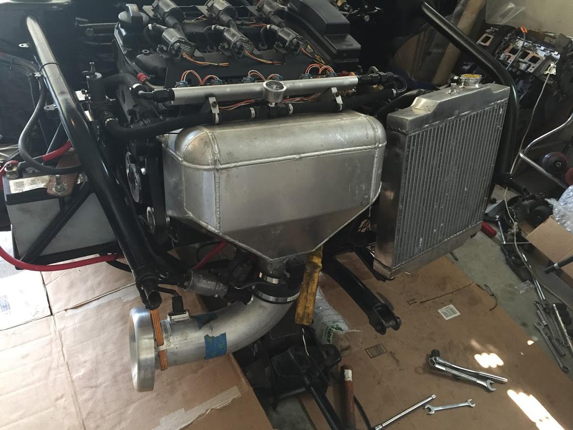
PS mine for the monster VR6 (~14-15" runners, 5.2L plenum, 82mm throttle body)

Curtis73 (Forum Supporter) said:
Agree... goal makes all the difference. Port EFI intakes (since they don't carry fuel with the inlet air) are a lot less sensitive since they have a lot less mass.
I often point to the LT1 intake. The cam was super mild (like sub-200 degrees mild), the torque peaked under 3000, but the intake runners were about 2.5" long with a huge plenum. If you went to the effort and expense to make a custom intake that was a better match to runner length and plenum volume, it is unlikely you would change the HP/TQ numbers more than about 5 in either direction.
If you're just looking to get a functioning intake that is a performance upgrade, you kinda can't screw it up. If you're looking to hyper-tune the last 3 hp out of it, then use maths.
Calculators can sometimes lead you down an interesting path, too. I used calculators to find optimal header primary length on a Caddy 500. It was something like 6.5 feet long. In truth, if I wanted to get the last 2 lb-ft of torque, I could have built some 78" long headers, but in practice, normal headers of any kind would have been an improvement over the factory manifolds. I only mention that so you don't get discouraged trying to fit 15" runners and 5' headers only to find they don't really improve things that much.
You have to be aware of everything too! For example a V8 has adjacent cylinders firing anywhere from 90- 180- 270 degrees apart. The cylinders 180 degrees apart will not interfere with each other the way cylinders firing 90 or 270 apart do. But you need to look at where each cylinder is firing in relationship to the start of the tail pipe. A typical cast Iron exhaust manifold is basically a log affair with little regard to where a exhaust pulse is in relation to each other.
We're talking about an intake manifold right? Why am I going on about the exhaust? Well, just like the exhaust everything on the intake side works in conjunction with everything else. Air has mass. Starting and stopping airflow reduces total intake and the amount of air an engine can intake is how much power the engine makes.
Treat each cylinder separately and you'll have a pretty symmetrical intake. But make less power than when you combine everything. Air heading to one cylinder goes from a dead stop to near subsonic speeds. Then the valve closes and what? You want it to wait around until the valve opens again?
Why not harness that energy to get an adjacent cylinder's air moving? Etc etc etc ?
Just like a header does? A pulse pushes the pulse ahead and pulls the pulse behind if they are combined at the right place like a good header does.

kitsune1324 said:
In reply to asphalt_gundam :
The calculators are awesome, thank you for the reference! I said it was a 3.8 as that's what it was initially (and it's easier to search), the engine has been stroked and bored to 4.3l. In the intake runner and peak torque calculator page, using the optimum runner size and length calculator, it asks for the number of induction wave..I can't really figure out what's it's asking for. Do you have an idea? The method will be CNC cutting the mounting plates, sheet metal/tubes for the ports and plenum, then I have a fabricator that will be welding everything together.
When you say to move the runner and radius it, are you saying to make it look more like this so it'll be able to pull air from more of the center than the side walls?

The induction wave refers to which....how do I put this....."bounce back" of the intake pressure wave you hope to "catch" at the same time the valve opens. Incase you don't know, air moves through an engine like AC current. It moves back and forth due to the pressure changes of the valves opening and closing. When and intake opens the air starts moving into the cylinder. That air has mass and therefore it has inertia (object in motion wants to stay in motion). When the valve then snaps shut the air/fuel then build pressure on the back side of the valve because the air further up the runner is still coming. Then the higher pressure air at the valve reverses its pressure wave up the intake runner to the plenum. Now the idea with runner length tuning is to try to get that wave (or another one) to be building pressure on the back side of the valve right when it opens again. This makes a dynamic supercharging effect. Same idea works on the exhaust side but with low pressure "pulling" exhaust out.
The way you moved the runner is correct to what I was getting at. Have the runner opening too close to the plenum wall and you effectivly shroud the runner just like a valve in a head. The uneven entry makes the transition a little messy (going to be more oval or rectangle than round, which is completely ok) but it can be made to work well. Look up a gutted and ported H22/H23 Honda intake and see what happens there. Just be aware there are some very poorly done ones out there that are not a good example. Good example is SBS Performance, amazing job and a buddy of mine. Has some great pics on the facebook page of both a gutted H series and the big bell mouth you want to have on other manifolds. https://www.facebook.com/Sbsperformance
Another great radius fab I have seen is to take aluminum rod of 1/2" or larger diameter and bend it around the runner and weld to create a bell mouth.
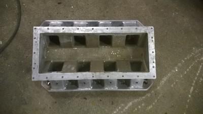
This is garbage:
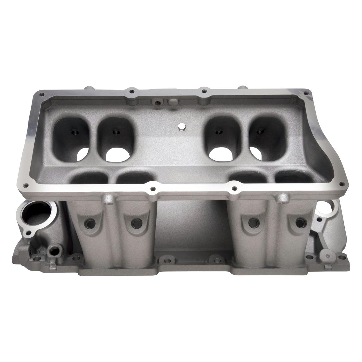
This is much better. See the bigger radius all around the port. (ignore the runner shape difference)
And Heavy porting to make an even bigger radius would make more power still.

Strizzo
PowerDork
9/16/20 1:14 a.m.
If you want dual runner, the 4.2 found in the f150s also had a dual runner setup, but people (like,two people) that did higher up setups would delete the flapper and have it run open all the time so there's probably not a lot to gain there

kitsune1324 said:
I think I'm missing out on the knowledge of runner length and plenum volume, I understand longer runners are better for lower RPM engines, but I don't know how much plenum volume can or will affect numbers, other than smaller pressure surges? I don't necessarily care to hyper tune, but I'm already putting in the work, so I want to make it work to the best of my ability. I know since the whole intake won't be cnc'd (unless I can somehow keep it around 1k), and humans aren't perfect, things won't be done 100% perfectly. I appreciate the info on the calculators. and not getting discouraged. From what I found recently, I think it's better to have like 13" runners but while trying to make sure this fits under the stock hood, it may not be possible without covering a large portion of the envine, and literally copying the stock intake manifold's U shape.
Plenum volume is an important consideration. It is all part of the system since the air is all connected.
Just like porting a head, you need the proper bulk flow, but you also need the right velocity. If you just randomly hog out the ports as big as you can you often lower the velocity to the point where you have defeated the harmonics as well as killed the inertia that helps trap the greatest amount of intake charge in the cylinder. Higher RPM engines tend to favor larger plenums since they have a larger air demand. There is more air reserve, kind of like a larger compressor in your garage. Lower RPM engines can sometimes take advantage of smaller plenums since they have the "time" to generate the velocity. The plenum becomes simply part of the flow path. A lower RPM engine benefits from a longer, smaller column of air being moved at a greater velocity. A higher RPM engine needs bigger supply to keep up with demand.
A metaphor: Take a weight. Let's say a 1/2" nut. Tie a long, skinny, wimpy rubber band to it. Pull the rubber band slowly across a table to drag the nut. The band stretches, the nut starts to move, your hand stope moving, and the nut continues to move as the stored energy in the band keeps pulling. You should be able to find a hand speed that makes the nut go the furthest distance. In the case of an engine, your hand is the piston, the rubber band is the air, and the nut is the resistance to flow. The speed of your hand is the RPM. Now switch the rubber band for a slightly shorter one and the nut to a 3/8". You'll find that your hand speed has to be faster to get the same result.
Switching to the 3/8" nut is like using a larger plenum. The shorter rubber band is the shorter intake runner. By messing with length, plenum, and size, you can see that the rubber band effect of the air favors different RPM ranges. In the case of the engine, you want the maximum amount of the rubber band to keep moving into the cylinder after the piston has reached BDC, just like the nut keeps moving after your hand stopped. In that way, shorter/bigger favors higher RPM.
Without hijacking the thread, I'd like to see some maths about how much harmonic/velocity effect is nullified by port EFI vs TBI or carburetor. The intake's harmonics have less effect with port EFI since the air isn't carrying the mass of fuel along with it.
I know many modern EFI intakes place less importance on the engineering of the intake and focus more on packaging, like in my LT1 example above. It's a low-RPM motor, but uses a large plenum and very short runners... but it doesn't seem to have much effect on the engine's output at all.
In reply to asphalt_gundam :
Got it, so fillet top, oval shaped runners are best. It's interesting because with the dual port heads, per cylinder, one port is a circle, the other is an oval-ish shape.
In reply to Strizzo :
the 99-04 3.8's were dual port, earlier engines weren't. SOme people have swapped over the f150 intake but it takes up a TON of space and typically requires a different hood.
Curtis73 (Forum Supporter) said:
Without hijacking the thread, I'd like to see some maths about how much harmonic/velocity effect is nullified by port EFI vs TBI or carburetor. The intake's harmonics have less effect with port EFI since the air isn't carrying the mass of fuel along with it.
I know many modern EFI intakes place less importance on the engineering of the intake and focus more on packaging, like in my LT1 example above. It's a low-RPM motor, but uses a large plenum and very short runners... but it doesn't seem to have much effect on the engine's output at all.
Yes the fuel adds mass but air has its own mass. It's what lifts tons of Jetliners off the runways. Think of it like water. It likes to go straight change it's direction and it will slow down. But more it hates to start and stop.
In reply to Paul_VR6 (Forum Supporter) :
Got it. I'll need to grab one of my spare heads and take a couple measurements then. I may end up following your professional advice, it's pretty difficult to fit the longer runners in this car, but I'll see what I can do. It all depends on the heads though.
A couple things that came up, since this car is dual runners per cylinder, am I able to take runner length 1 and add it to runner length 2 to get the total runner length? I doubt it'll work like that but it's just a thought. For the second style I was working on, I probably can't have each runner cross the center, I might only be able to have one long runner, the other would be very short, unless it's okay to have a very large, single runner that splits into two as it reaches the head.
In reply to frenchyd :
How owuld you recommend harnessing the energy to get an adjacent cylinder's air moving? Would a short runner/long runner intake with a cross through the center to that as it keeps air flowing on both ends?
In reply to kitsune1324 :
What's the firing order?


