Ok. I'll give you a quick primer.
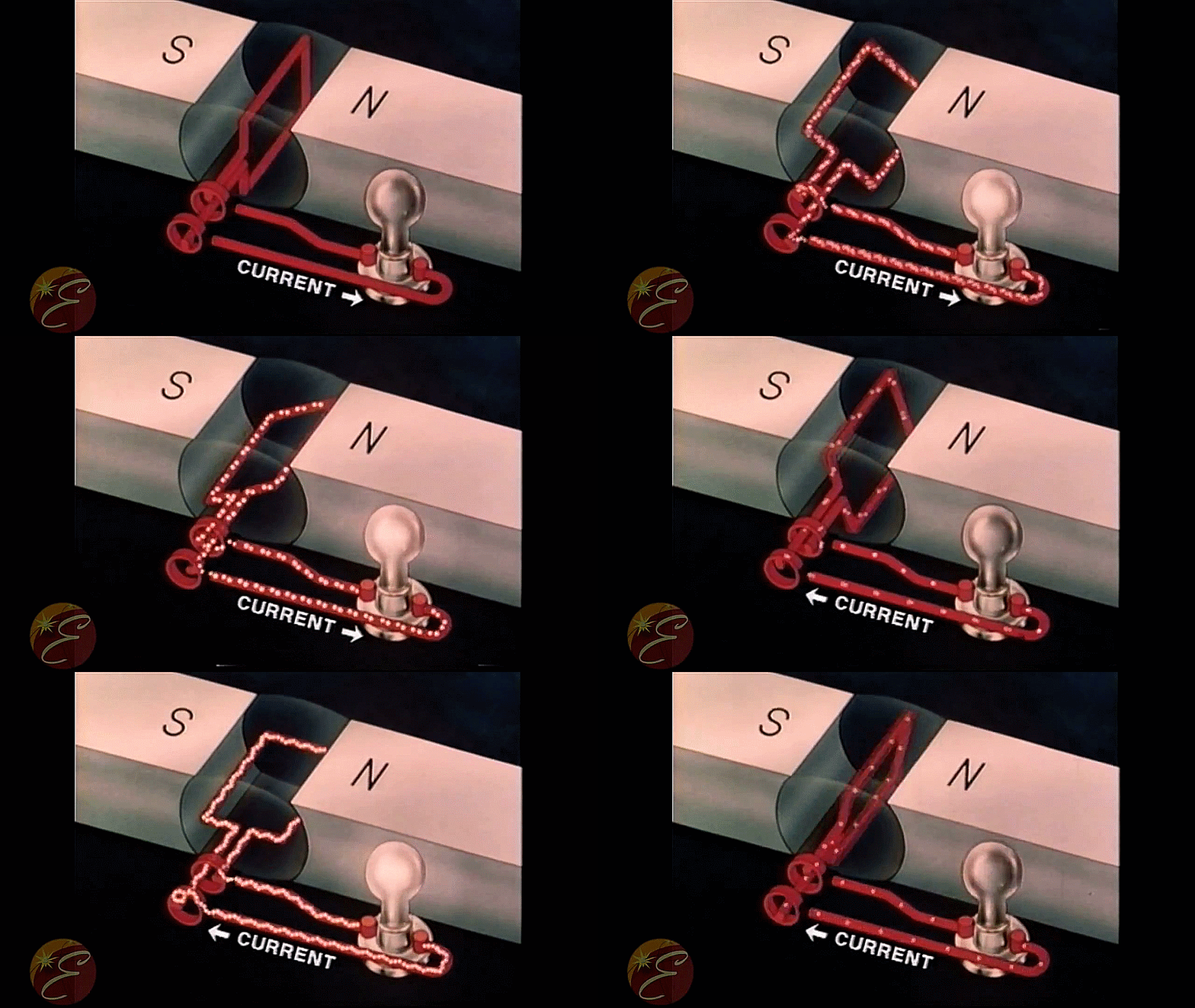
DC flows one way. AC flows both at about 60hz. That's why many AC appliances hum on the same note.
AC is generated by big generators much like the alternator in your car, the only real difference is that the alternator in a DC system uses diodes to only "push" and not "pull." This way, home electric can be transmitted through one conductor and uses the actual ground (the earth) as a ground, much like your car's battery negative terminal is connected to the frame.
Each component in your house is powered through two or three wires. The black is the "line" and the white is the "common." They are called this (instead of hot and ground or positive and negative) because 60 times per second, the flow reverses and the white is carrying juice backwards, so the term negative doesn't really apply. If you open your breaker box, chances are you'll see that the whites and the greens (or bare coppers) all go to a common bar which goes outside and connects to that copper bar stuffed in the ground. What comes in overhead is the line. In this way, the green or bare copper is a redundant ground in case the white common conductor becomes compromised. Let's say your fridge gets a loose white wire somewhere in the wall. If if doesn't have the ground wire, there is voltage potential between the chassis of the fridge and another conductor... like your hand touching the fridge and the sink at the same time. Zap.

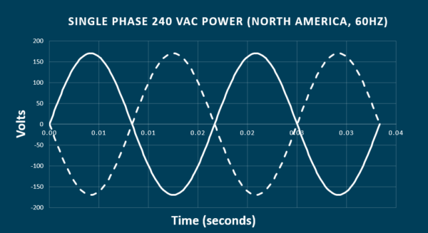
The way most houses are wired, they have 120v and 240v. The breaker panel has two 120v lines coming into it. These two lines are on opposite phases (shown below)

Each one of those lines represents each one of the "lines" coming into the panel. (usually black and one other color like blue or red). So let's say your panel has black, red, white, and green. The solid line is black, the dotted line is red, and the straight zero line is white/green. If you test between black and white (or black and green) you will get 120v. In the picture above, (disregard the numbers for now to avoid confusion) you can see that the waves peak at 120v, so the voltage potential between any one line and any one white/ground is 120v. Now if you test between the two lines (black and red), you see they are both at opposite 120v peaks. Since they are both "pushing" with 120v of force, the net voltage is 240v.
Now, look at this picture

The two lines coming into the house from the power company, (Hydro for you hockey-loving Maple-leaf people) black and red, attach to the top of these copper strips. The breakers snap onto those strips. They alternate so that each breaker bay gets an opposite phase. When you open your breaker panel and see a double breaker, you know it is a 240v circuit because the breaker attaches to two different lines.
For most household things, it's pretty easy to determine loads. If you're adding a circuit, you can throw a breaker in an empty bay and run new conductors, or it is also possible to simply source power from an existing nearby circuit. In a recent example, I wanted to add an exhaust fan in my bathroom. The circuit it was on contained bathroom light, bedroom lights, and bedroom wall outlets. It was a 15A breaker with 14-ga wire. I was able to just run a conductor from the bathroom vanity light above the ceiling and add the exhaust fan. I just added up all the possible loads (two 60w sockets in each bedroom, three 60w sockets in the bathroom for a total of 420w that could be stuffed in the lights. 420w / 120v = 3.5A. That saves plenty of amperage for the outlets, and the LED exhaust fan I wanted to add was something ridiculous like 0.25A. Bingo. Borrow from an existing circuit.
Now look at this compared to the naked breaker panel above:

This is pretty typical. You can see the black and red big wires coming into the top. All of the single breakers connect to a single phase of 120v on the lug hidden behind it, and all of the double breakers connect to two individual 120v phases meaning that between the two wires you get 240v. You can also see all of the whites and coppers connecting to the common bus bars on the sides.
This panel has only one 240v circuit (see near the top on the right, there are two switches with a tie-bar). In this case, they wired it typically, using more of the same household NMB wire. You can wire a 240v circuit just like this using the white as the second line, but I (personally) like to toss some color of electrical tape on both ends of the white. This means I will always instantly see when I pull apart a junction box that the white is being used as a line and therefore I know (at least in my house) which circuits are 120v and 240v.
The rest follows pretty typical electrical theory; make sure you use the right gauge conductor for the breaker size that backs it up. Typically 15A gets 14ga, 20A gets 12ga. From there on up, just consult a gauge/amperage chart.
For the most part, electricity is electricity. Just know that the AC changes direction 60 times per second, and it is 10-20 times the voltage of what's in your car. It stings. In life-ending or fire-causing ways.
As far as proper household wiring techniques and procedures, I'll defer to some of the actual pros here. I know the engineering and mechanics. I'm not the guy to go to for actually knowing the electrician's trade.


