We’re building our LS1 with a super-stout forged crankshaft from K1 Technologies, but before we could install it, we needed to balance it. In a nutshell, crankshaft balancing attempts to counteract the forces on a crank as it spins, meaning the weight of the connecting rods and pistons, as well as the piston rings, oil, bearings, and everything else. For our lightweight rods and pistons, this meant we’d need to remove some material from our crank’s counterweights.
Let’s start with a disclaimer: this probably isn’t something you should attempt at home. The machine we used costs as much as a new car, and used balancers start well into the four-figure range. How’d we get access to this fancy balancer? We signed up for an engine rebuilding class at our local tech school, Daytona State College.
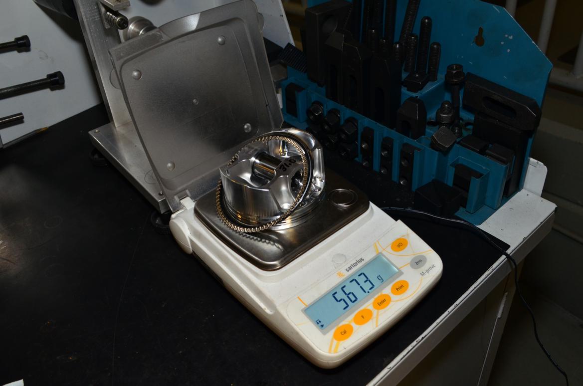
So, step one: weigh and measure. We weighed each end of our connecting rods, along with our pistons, rings, bearings, wrist pins, and wrist pin retainers. After running those numbers through a few formulas from our instructor, Gordon Johnstone, we came up with a target for our bob weights: 1708.3 grams. That number represents the theoretical amount of mass on each bearing journal that will need to be counterbalanced as the crank spins. It’s worth noting here that crankshaft balancing is an imperfect science, and it seems like every engine builder will have their own special formula to get that “perfect” balance. The reality is that there are so many variables, it’s pretty much impossible to perfectly balance your engine. But dammit, we were going to get close!
Once we picked the right assortment of weights to equal 1708.3 grams, we attached our four bob weights in place of connecting rods, placed our crankshaft on the machine, and went to work. The actual balancing process is easy: Let the machine spin the crank, then drill a hole in the counterweight where it says weight needs to be removed. We tried to keep our drilling as close to the actual imbalance as possible, as removing material from the back of the crank to correct an imbalance up front (or vice versa) just adds extra stress when the engine is running.
Did we win? Nearly. By the end of the evening, our rotating assembly was balanced to within a gram. That’s pretty darn good, so we cleaned the metal filings and lube off of the crank, and put it next to the engine for final assembly.
Comments
clshore
New Reader
2/6/18 6:50 p.m.
It's worthwhile to note that balancing symmetrical motors, like flat, or inline, requires no bobweights.
It's the vector sum of forces from two rods on one crankpin on V style motors that introduces the need for bobweights.
So it's about an order of magnitude simpler.
This is one of those jobs I always pay the man to do. I found that balancing the rotating assembly of a motor greatly improves durability. Every motor I built for endurance racing was balanced. I attribute never having one of the motors I built fail to balancing. 8, 10, 12, & 24 hour races will find motor issues for you. I always felt by balancing the rotating assembly you are reducing or eliminating forces on the motor that cause failures. I have no actual proof of this but our 4age motors were seeing 8k rpms regularly in these races.
Displaying 1-2 of 2 commentsView all comments on the GRM forums
You'll need to log in to post.


