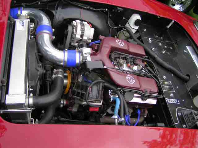
An engine won’t last long without some sort of air supply. And for a cross-pollinated engine swap project like our Miata-powered MGB, the solution isn’t going to come from the catalog.
Until this point in the build, we’ve stayed pretty true to one self-imposed restriction: All of the parts used for this swap have come from either the Mazda or MGB parts bins. But now it’s time to wander off course a bit as we prepare to install a supercharger.
Fast Forward obviously doesn’t offer a supercharger package specifically for a Miata engine fitted in an MGB–although the folks there were very helpful in offering us a mock-up setup to test-fit before we purchased–so we were on our own for some parts of the kit and installation. We picked a kit for a 1994 Miata (our donor car) and made modifications as necessary.
Go With the Flow

When it comes to air intakes, everybody seems to be an expert, especially on the internet. People commonly jump to the conclusion that cold air trumps everything. However, thousands of dyno pulls have showed us that cold-air intakes only help when they flow air well. In other words, flow generally trumps temperature.
When it comes to small engines, like those in MGBs and Miatas, a 20-to-30-degree increase in intake air temperature usually corresponds with a mere 1-horsepower decrease at the wheels. Meanwhile, flow issues can cost 10 horsepower pretty quickly. To translate this wisdom into strategy: Design your air intake for flow first, then look to lower the intake temperatures.
We’ve also found that a well-placed heat shield can make almost as much of a difference as a full cold-air intake. In our experience, underhood temps near an unshielded air intake often reach 150 to 250 degrees. A heat shield can drop them by as much as 60 to 80 degrees.
A full cold-air intake may lower temps by another 60 degrees, but that’s not as easy as it sounds–especially when the intake is located at the back of the engine, like it is with our kit. With a setup like ours, the throttle body can absorb another 30 to 40 degrees of heat from the engine bay.
DIY Flow Bench

You’ll note we’re using actual, measured temperatures in our analysis. That’s the great thing about working with intake temperatures: They’re easy to measure.
Measuring flow, however, is more difficult–unless you have access to a flow bench. And we do.
We built our own flow bench using Flow Performance’s Basic 2.0 Flow Bench Kit. The $997 bundle includes the necessary flow rate processor, flow element and Windows-compatible software. We just needed to add a shop vacuum and a cabinet, both of which we sourced from our local big-box store. For about $1200 plus a laptop, this setup offers an easy way to get accurate, repeatable flow data.
Tubes and Turns

Time to build and test our intake. We assembled several pieces of 2.5-inch tubing, bends and connectors that would mate to our 2.5-inch mass airflow sensor. After test-fitting each setup to the car itself, we ran them on the flow bench. We also baselined the air filter and the MAF with its coupler to show how our various tubes and bends influenced airflow.

Before heading to the flow bench, we mocked up several options to test. We had the highest hopes for the long-runner configuration, which would obviously duct in cold, ambient-temperature air. In addition to these setups, we also tested different runner lengths.


To satisfy our curiosity–and provide even more valuable information to you, our faithful readers–we also tested some intakes using flexible hose. We were trying to replicate the home-brewed intakes we’ve seen. The results, as you can see on the chart below, weren’t pretty.
The results didn’t surprise us much, as we’ve learned two basic rules about air over the years. Rule 1: Air doesn’t like changing direction very much, so a straight shot is better than a curve. Rule 2: Air doesn’t like changing shape drastically, so it’s important to keep tubing the same size or use very gradual transitions.
A few facts stood out, though. First, the air filter alone flowed better than just the coupler and MAF, yet it didn’t flow as well when attached to the MAF. The end of our filter was capped, so that was likely restricting some flow. Without the cap, that 512 CFM figure would probably be higher.
The data also showed that Rule 1 is very true: Air doesn’t like changing direction, as each 90-degree bend had a measurable negative effect.
Once we started adding the various runners to our 180-degree bend, we saw some surprising results. Considering that the longer runners tended to perform a little worse, it’s interesting that the 12-inch runner actually outshined a setup that didn’t feature any runners. We can only surmise that the 12-inch runner offers some form of ram tuning, at least on the flow bench.
Drawing Conclusions

While the flow bench data helped us predict some things, the dyno will provide real numbers. Once the car is running and tuned, we’ll likely retry some of our setups to see how tightly the flow bench data correlates to power on the ground. Getting the air cooler, whether through a heat shield or one of the less efficient intakes, will be part of our retesting. We may also try out some tapered runners–following Rule 2–to see if we can regain any of our losses. In the meantime, we know that our straight-shot setup will be a great place to start.
The big take-home lesson from this project installment? No matter what your situation, some DIY flow bench testing can help you build an efficient air intake setup.

The straight-shot intake was our clear winner. However, we saw one more potential issue that was worth another trip to the bench. This setup put the filter up against the firewall and 2 inches above an underhood shelf.
We wanted to make sure that those nearby obstructions wouldn’t affect our numbers, so we simulated them with some cardboard and retested. Result? No difference. In fact, we actually picked up about 2 CFM.
That small amount of airflow probably wouldn’t make a power difference at the rear wheels, but it’s a good reminder that air doesn’t always do what you expect–so measure where you can.